I recently purchased an external floppy drive the for the Amiga which was sold as “untested”. Unfortunately “untested” in this case meant “doesn’t work and someone did a bad attempt at repairing it”. There were parts of the drive physically broken and it was beyond repair. I lucked out because unlike the Rotec drive I repaired in the past, this one uses a standard floppy connector inside. So, instead I decided to convert a PC floppy drive to work in the case.
Amiga floppy drives are wired a little differently to PC ones, they use a modified version of the Shugart standard. In particular the following things are different to the IBM/PC standard:
- PC floppy drives are set to DS1 (Drive Select) whereas Amiga uses DS0
- PC floppy drives use Pin 34 of the cable for DC (Disk Change), Amiga uses Pin 2
- Amiga uses Pin 34 for RDY (Ready to access), PCs don’t have this, DC assumes RDY in PC
- PC floppy drives map density (DD/HD) to Pin 2, Amiga only supports DD without a special half-speed drive and software support
I happened to have a working Samsung SFD-321J floppy drive. So I decided to modify this drive. There are guides all over the internet on how to modify drives. Some are as easy as selecting jumpers, many (like mine) require soldering. Unfortunately I could not find a guide for my specific model, but luckily it was very easy to figure out.
Using the labelled areas below, this is what I did:
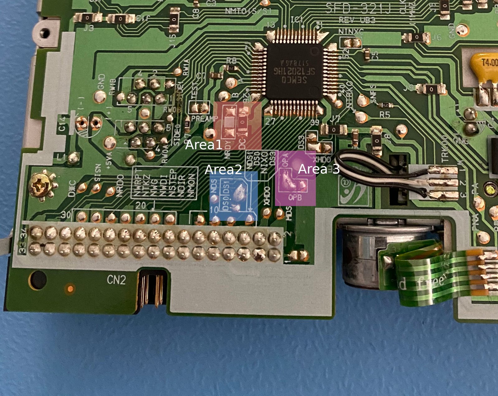
Area 1
This area is essentially a jumper select for pin 34. It uses a 0 ohm resistor to select DC as the pin’s output. Using flux and a hot-air gun I desoldered the 0 ohm resistor from DC, then carefully resoldered it in RDY.
We do need the DC signal for pin 2 so I soldered a wire there for Area 3.
Area 2
This was a giant solder blob between the middle pin and DS1 at the top, using some solder wick this was removed very easily. Since the gap was large I decided to use a tiny wire between the pins for DS0 and solder that in place.
Area 3
This area is the option select for pin 2. It was set to OP A which is the disk density selection, OP B I believe force DD. Again this was just a giant solder blob which was wicked-up easily. We want this pin to be the DC so the wire from Area 1 was soldered to the middle of this area which is directly connected to pin 2.

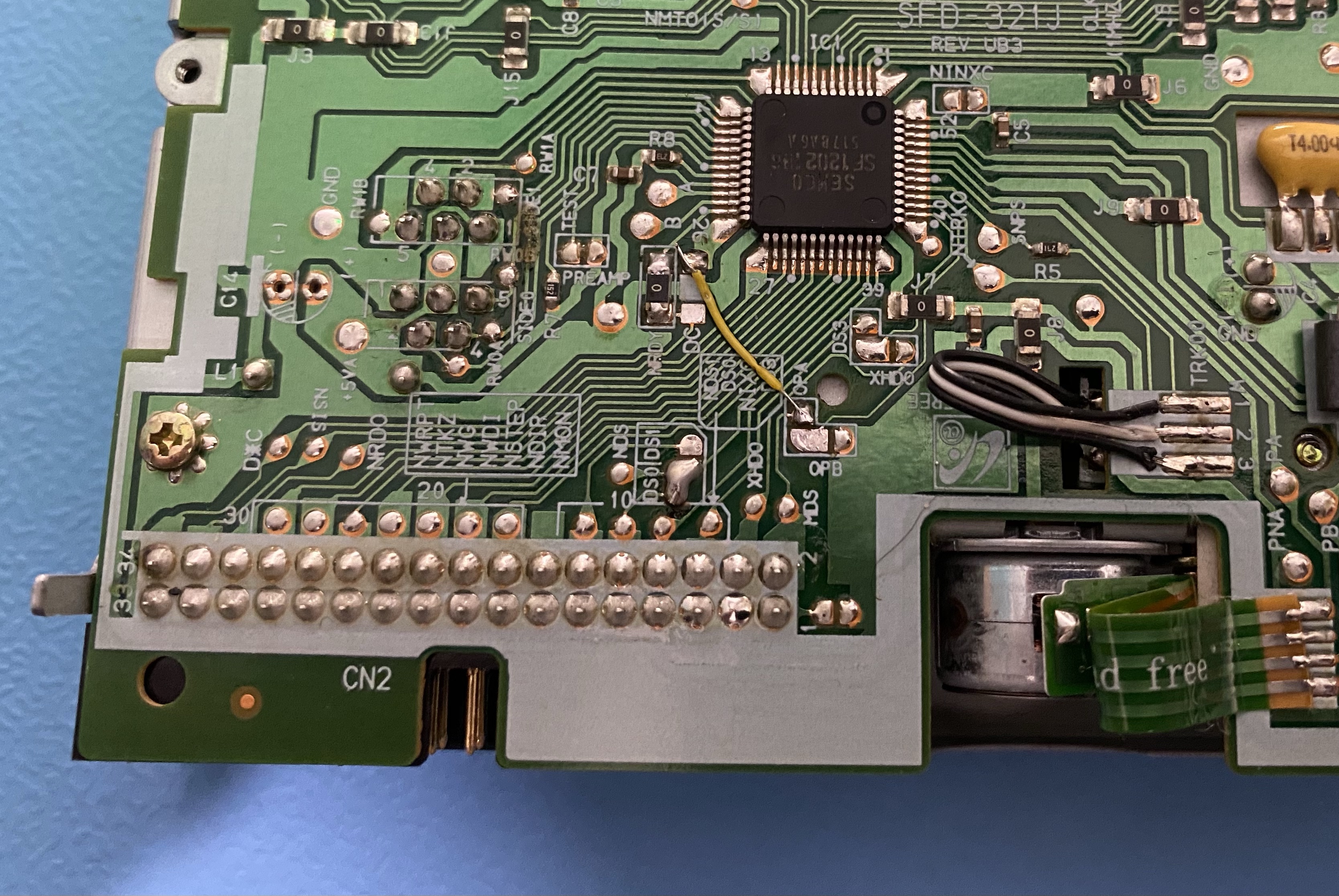
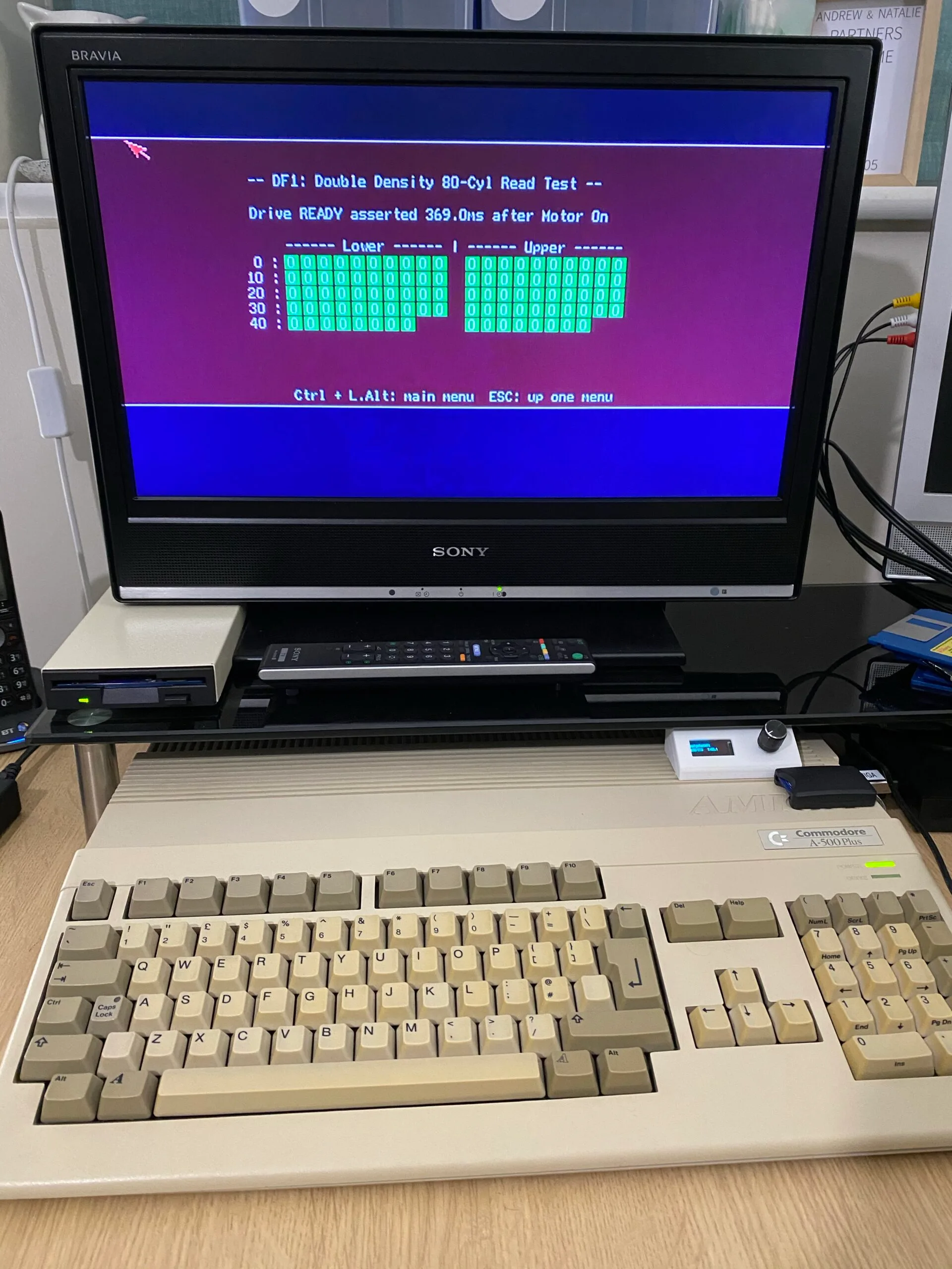
The image above is the final result. I also made sure the drive heads were clean and re-greased the worm gear for the heads. After reassembling I ran a few tests and it appears to work. I now have a real floppy drive to use alongside my Gotek!

What was the model name of the PC drive? This is not as useful as it could be without this information.
LikeLike
Found it. Sorry
Samsung SFD-321J
LikeLike
Good article! Really helped me to re-educate myself on this and good choise on the drive model.
Minor correction: The word “middle” is incorrect it should be “top”.
For “Amiga only supports DD” I would say “converted PC drive in Amiga only supports DD” since Amiga supports HD with special half speed high density drives.
One old source says “Ground the HD detection signal, but only if there is no pad to change from D.C. to RDY”. I have hard time to understand what that means.
Another old source says RDY signal is not needed for most use in Amiga, but for Xcopy program that refuses to work without it. Ofcourse full compatibility is high priority and RDY must be added, but I believe some old drives seem to lack this signal in their controller.
Two things puzzle me also if PC has two FDDs are they both set to DS1 or is drive B: set to DS0?
Also when installing converted drive to external DF1: case, should it be DS0 too or keep it DS1?
What is that test program in the last picture?
LikeLike
Thanks!
I’ll check out the corrections shortly.
I’m not sure about the RDY signal, I’ve heard some external drives don’t use it but that Gotek drives require it.
PC drives are both set to DS1, their cable has a twist in it which shifts the DS lines. Likewise Amiga drives sort out the drive select lines themselves (so you can daisy-chain external drives) so they should all be set to DS0. There are exceptions to this with some machines with multiple internal drives.
At the end is Amiga Test Kit, I highly recommend this tool to test anything Amiga: https://github.com/keirf/Amiga-Stuff/releases
LikeLike
Conversion must be ok, but still I wanted to do understand what is “OP A” and “OP B” functions really. I found this:
Click to access SAMSUNG-SFD321B-070103.pdf
It is for older SFD-321B model, but most of things are same.
OP A is for 3 Mode usage
OP B is for 1.6MB usage
“OP A” connected and “OP B” open is 3 Mode (1MB / 1.6MB / 2MB) This the situation before conversion
Both “OP A” and “OP B” open is 2 Mode (1MB / 2MB) This the situation after this conversion
“OP B” connected and “OP A” open is 2 Mode (1MB / 1.6MB) It would be intreasting to see what this would do with conversion.
Also notice CN2 connector pin 1 solder pad with “OP B” copper area. Should this be bridged in this situation which would mean grounding “OP B”? Who knows since the manual is not that detailed.
LikeLike
Off the top of my head the OP mod here removes access to the switch and holds pin 2 (density select) always high. Which means always low density disks. It has been a while since I did this mod though, my memory of it all is a bit fuzzy.
I’m not sure how OP B would work unless there is a pull resistor somewhere.
LikeLike