This one could potentially fit in the restoration series as this is around a problem I found and how it was solved. But it centres around one of the upgrades, so I’ve made it an “upgrades” post.
The Problem
I had a weird issue with the RiscPC where on the first boot the resolution seemed locked at 640×480 256 colours and could not be changed. Almost like a safe mode. Once rebooted everything worked fine. It was only happening at power-up.
I initially made the assumption that the RiscPC was starting up too quickly to get the monitor ID properly, so I raised a question on the StarDot Forum (warning, spoilers for this blog post in the replies).
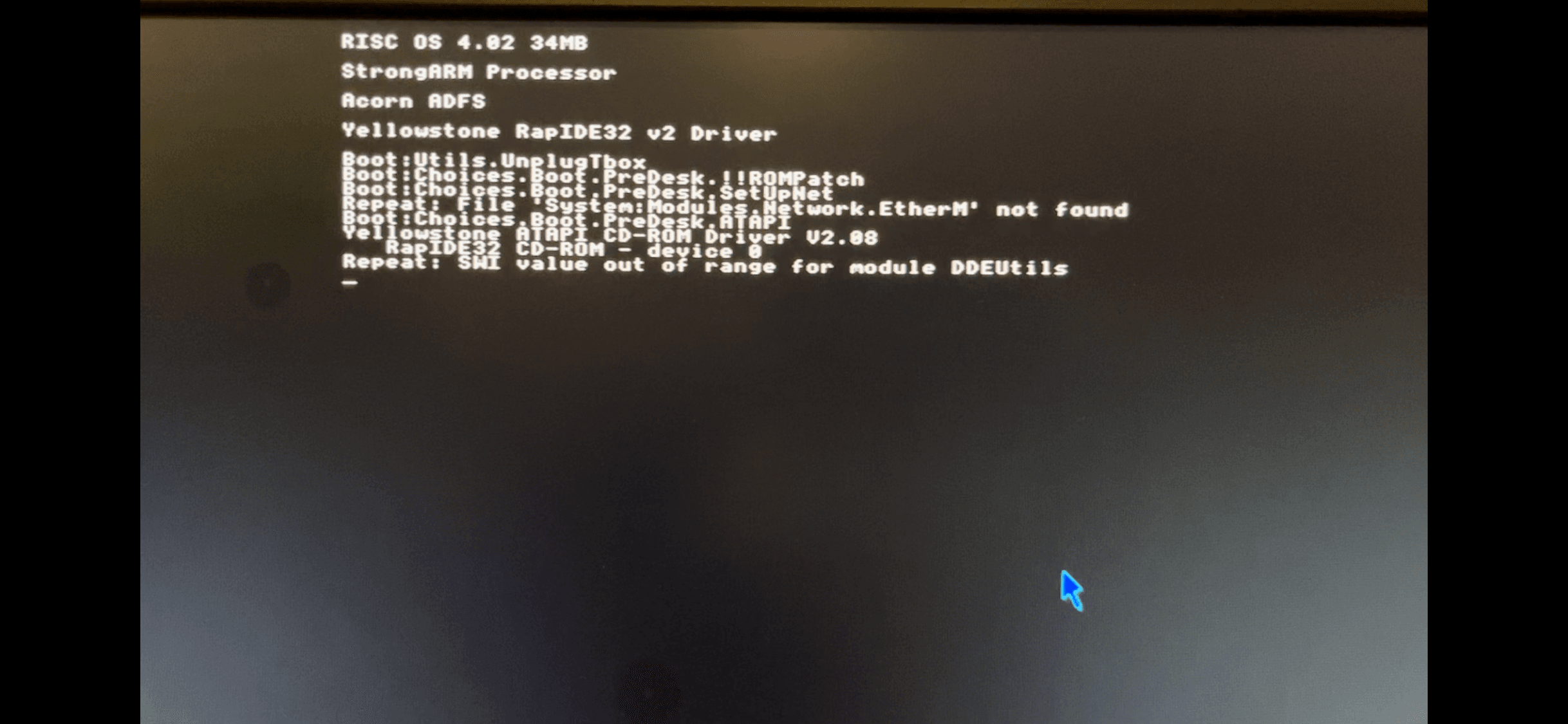
The only other symptom was a few strange boot messages.
Diagnosis
Forum member Ian Jeffray pointed out that the reason the resolution was fixed was not that it couldn’t detect the monitor, but that it was in a form of safe mode because booting did not complete properly.
I downloaded a tool called !Reporter which records the boot messages for you to review once booting is complete. This coupled with the screenshot above pointed towards an issue loading “EtherM”.
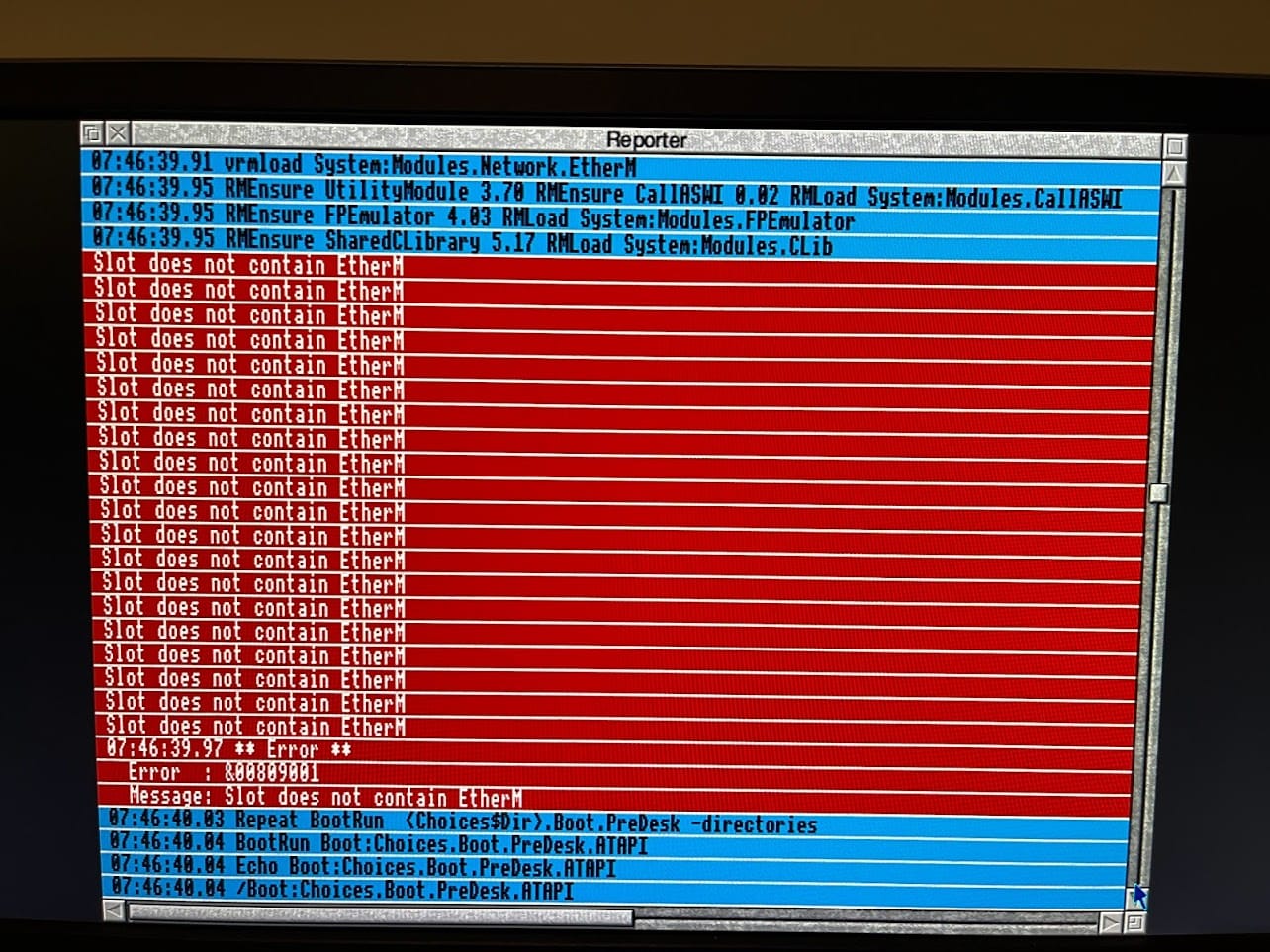
EtherM is the driver for the Ethernet module in the system, and indeed this was missing on cold boot, but visible on a warm boot.
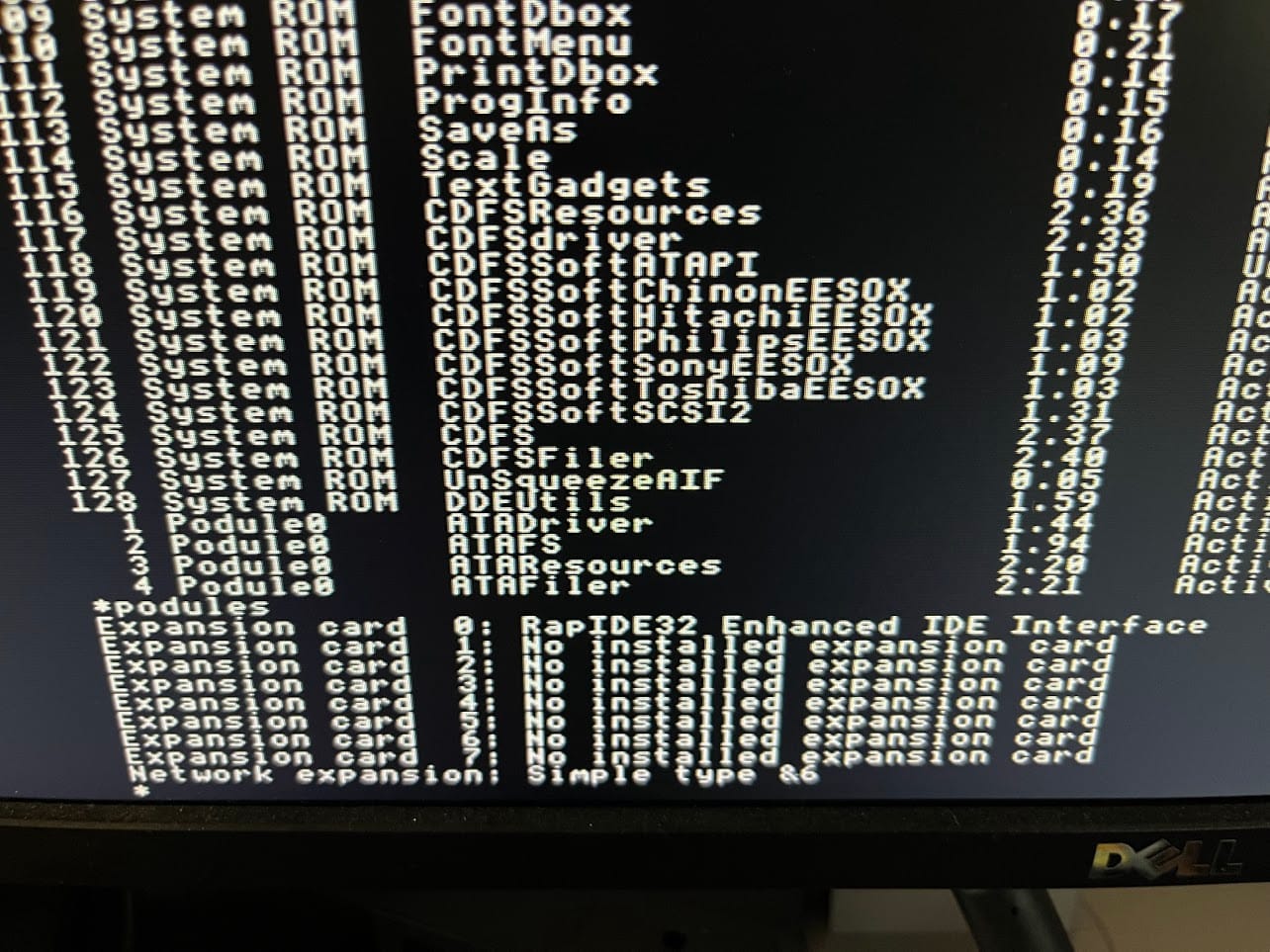
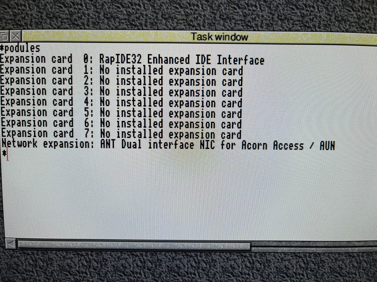
The driver is built-in to the ROM of the module, so it should “just work”. Something is stopping it from being loaded on boot. This in-turn was causing the safe-mode-like behaviour.
Fault Finding
The initial suggestion was that the power-on reset circuit might be faulty. This is an RC delay circuit which holds the reset line for a short time during power-up. I checked this out and the capacitor had good capacitance and ESR. The resistors were unlikely to fail, but I checked them out too and they were also good. I also checked the the capacitors on the module itself just in case a poor ESR was causing some power-on issues. These again were well within spec.
Whilst probing the module I noticed a jumper next to the connector that plugs onto the motherboard. I wondered what it did so I buzzed it out.
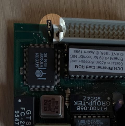
This is where things got weird, the top pin in that photo was buzzing to a pin on the connector, but the middle pin wasn’t. I measured the resistance across the jumper and it was in the region of 50K ohms. OK, that might be a problem. I’m assuming the jumper was damaged or dirty, either way I pulled it, threw it away and replaced it with a new one. Now reading 0.01 ohms across the link, which is much better.
I put the module back into the RiscPC and it worked immediately on the first boot!
It was more luck than anything else that I found this fault and luckily it was an easy one to fix. I still am not quite sure what the jumper is for, but the high resistance likely means the signal was not reliable.


Leave a Reply