Whilst I do like working with STM32 development boards, some basic information I need can often be buried in pieces of documentation, videos and examples.
Today I wanted to simply echo “Hello World” to the built-in ST-Link UART, running on bare metal. This post might help others, but it is also to help me remember for next time.
Starting point
First of all, you need your STM32MP135F-DK board, a USB-C cable and a micro-USB cable.
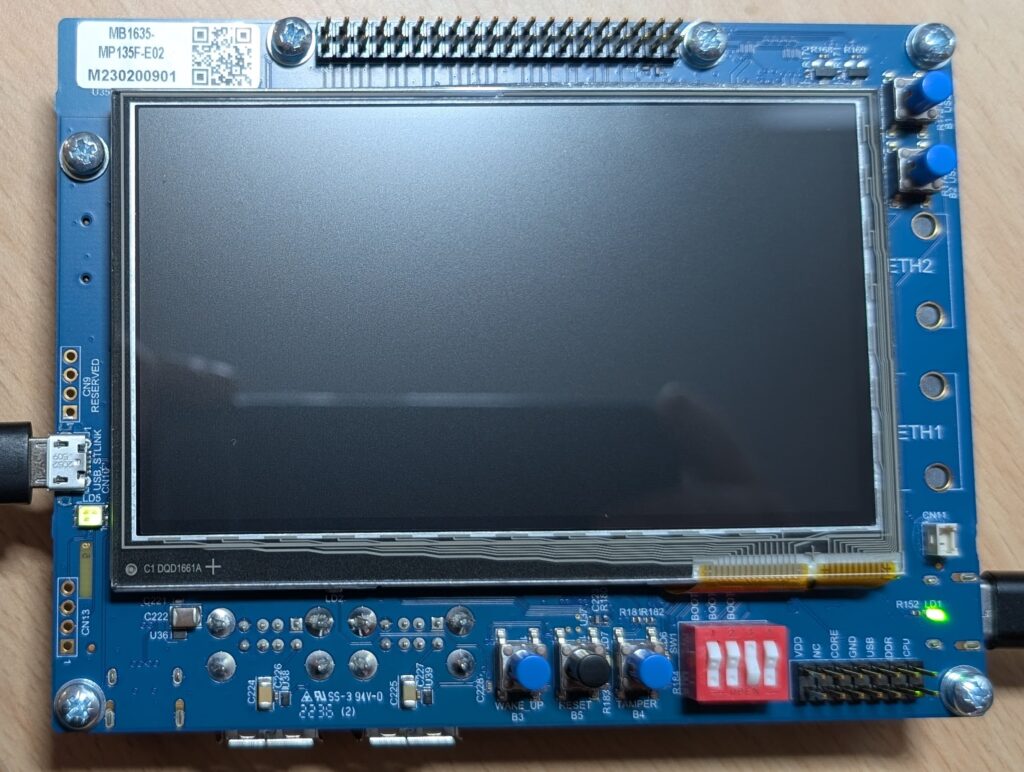
The USB-C goes into the right-hand side and should be capable of providing 5V at 3A. The micro-USB goes in the left-hand side and is the ST-Link communication to the computer.
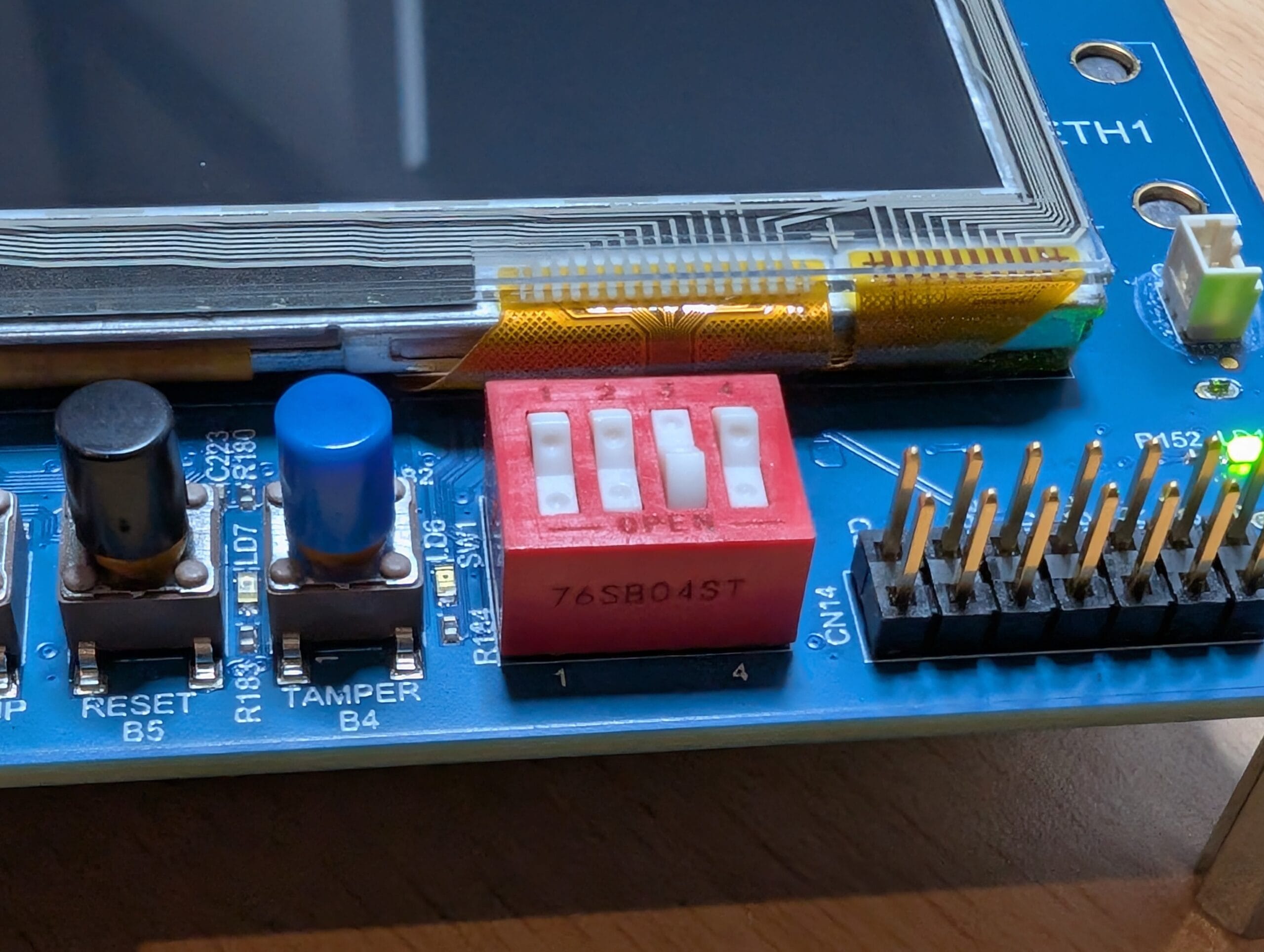
Next you need to set the jumpers. This configuration sets the board into “Engineering Boot” mode, which allows it to boot from whatever is loaded into the ST-Link, rather than the default SD card boot.
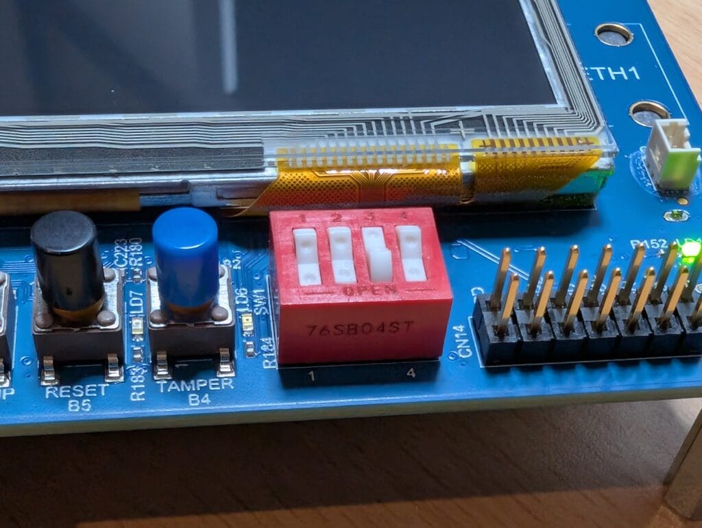
Hardware setup
Now to create the project in the IDE. A lot of information here is based on the STM32MP13 demo video, with pieces I’ve gained from example code and past experience.
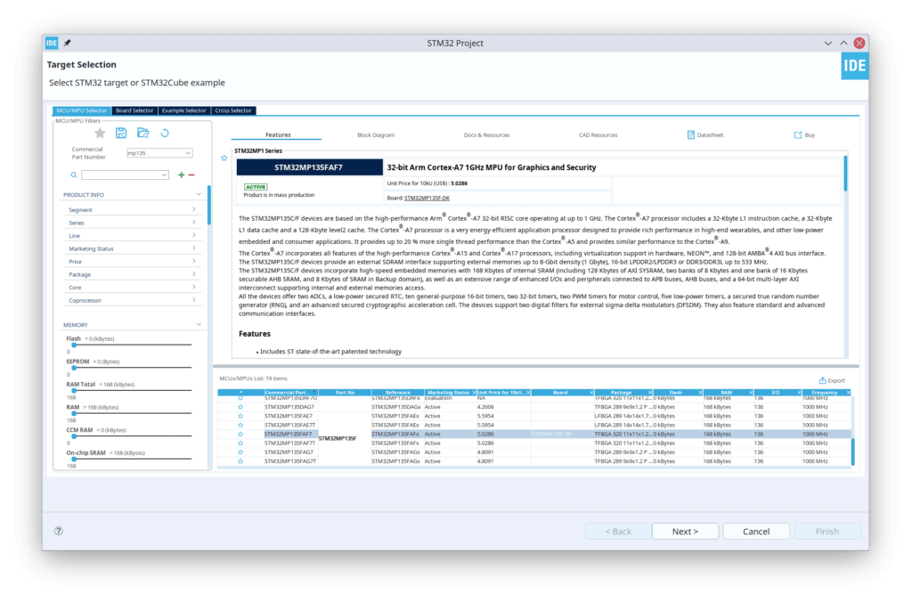
The first thing you need to do is create a new project in STM32CubeIDE. If you search for MP135 you should find the chip easily. Whilst you can create a project for the board instead of the chip, this enables everything that is on the board, which is a lot if you don’t want it all.
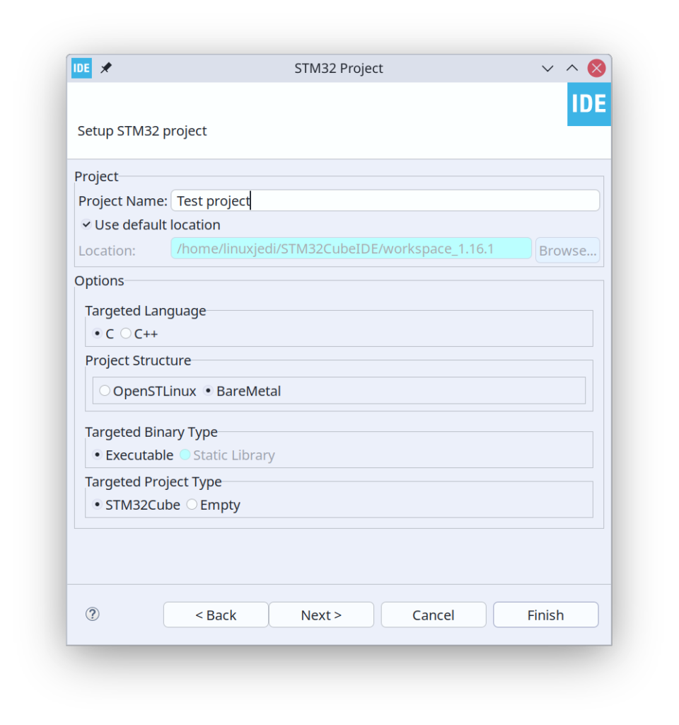
On the next screen, make sure you select “BareMetal” as the project type.
GPIO LED
Then, after a little time, you should get the Device Configuration Tool screen. From here find PA13, you can use the search at the bottom to find it. This is connected to one of the LEDs on the board. When you left-click you can make it a GPIO_Output.
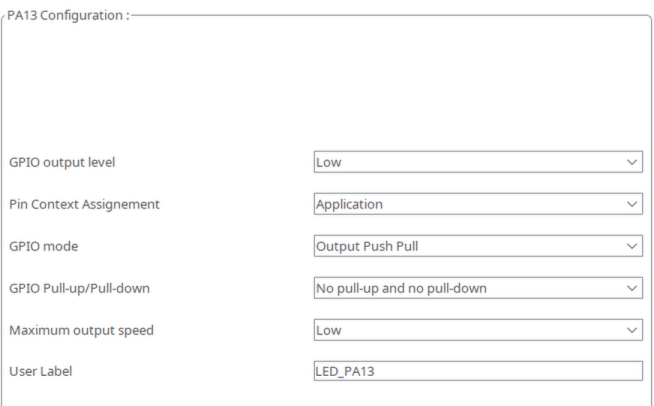
Under the “System Core” select GPIO and you should see your pin there. I have given it a label “LED_PA13” which will be useful when we get to the code. Make sure the “Pin Context Alignment” is set to “Application” for that pin.

For more GPIO connections, ST have a wiki page with details.
UART
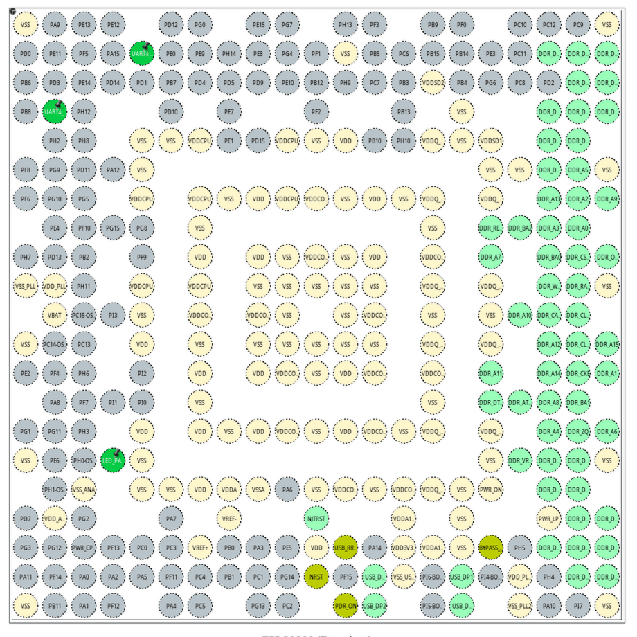
This part took me a little while to figure out, I eventually found it in the source code of an example. The ST-Link uses UART4 on pins PD6 and PD8. If you find those pins and click on them, you can make them UART4 RX and TX.
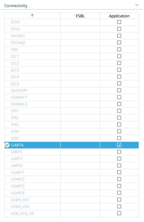
In connectivity, you can tick “UART4” to enable that in the HAL, then click on it get into the mode menu to enable “Asynchronous” mode.

At this point, we are done with the hardware setup and can write some code.
Software
A lot of this is based on one of my previous blog posts about getting UART to work as stdout on an STM32. Find main.c and make the following changes.
In “USER CODE BEGIN Includes”:
/* USER CODE BEGIN Includes */
#include <stdio.h>
/* USER CODE END Includes */
In “USER CODE BEGIN 0”:
/* USER CODE BEGIN 0 */
#ifdef __GNUC__
int __io_putchar(int ch)
#else
int fputc(int ch, FILE *f)
#endif
{
    HAL_UART_Transmit(&huart4, (uint8_t *)&ch, 1, 0xFFFF);

    return ch;
}
#ifdef __GNUC__
int _write(int file,char *ptr, int len)
{
    int DataIdx;
    for (DataIdx= 0; DataIdx< len; DataIdx++) {
        __io_putchar(*ptr++);
    }
    return len;
}
#endif
/* USER CODE END 0 */
In “USER CODE BEGIN 2”:
  /* USER CODE BEGIN 2 */
  setvbuf(stdin, NULL, _IONBF, 0);
  setvbuf(stdout, NULL, _IONBF, 0);
  setvbuf(stderr, NULL, _IONBF, 0);
  /* USER CODE END 2 */
Then in “USER CODE BEGIN WHILE”:
  /* USER CODE BEGIN WHILE */
  while (1)
  {
	HAL_GPIO_TogglePin(LED_PA13_GPIO_Port, LED_PA13_Pin);
	printf("Hello world\n");
	HAL_Delay(1000);
    /* USER CODE END WHILE */
What we have done here is:
- Redirected one of the underlying functions used by
printfto the UART - Removed buffering, so everything is printed immediately
- In the forever loop, toggle the LED on and off as well as print “Hello World”, then delay for 1000ms.
This is all the code level things we need to do, you can upload the code at this point and will see LD4 on the board flash once a second.
Minicom
Of course, my laptop runs Linux, so I use Minicom as a serial terminal. I’m not using a return carriage character here, so I create the file ~/minirc.dfl with the following contents to automatically add carriage return on line feed:
pu addcarreturn yes
The ST-Link will create two ports on the machine, the UART is exposed as the lowest one, which is /dev/ttyACM0 in my case. This can be connected to using the following command:
minicom -b 115200 -o -D /dev/ttyACM0
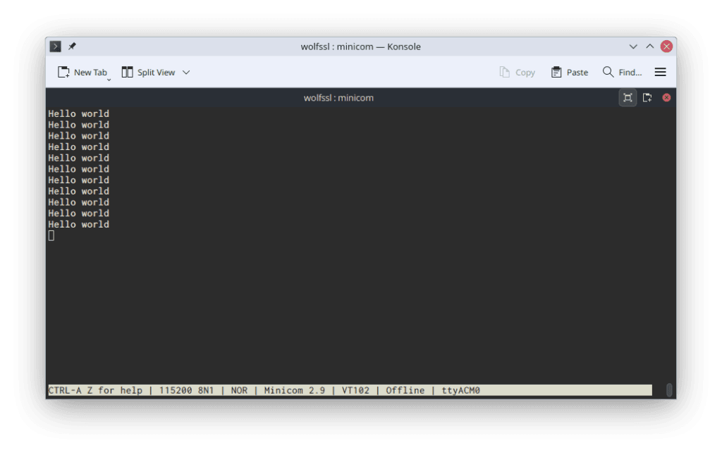
From here, you should see “Hello world” echoed once a second to the screen.

Leave a Reply