
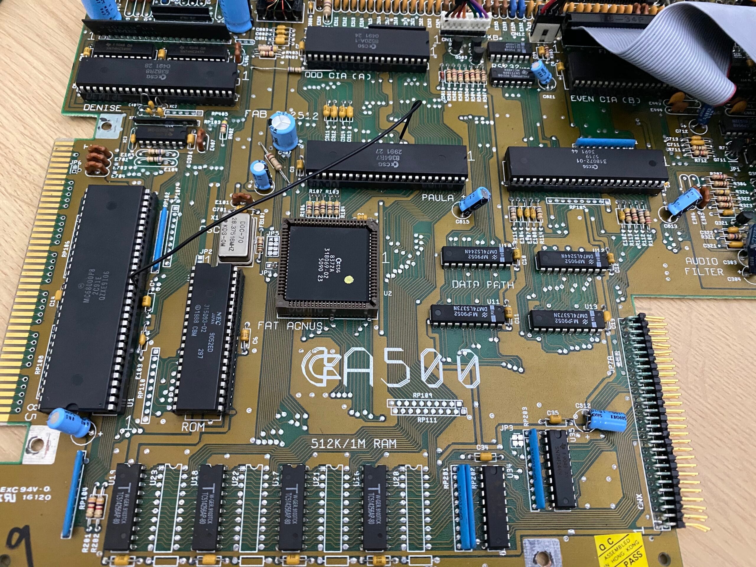
Someone asked me how I diagnosed the break in the PCB trace of the Amiga 500. So I thought I would go into a little more detail in this blog post.
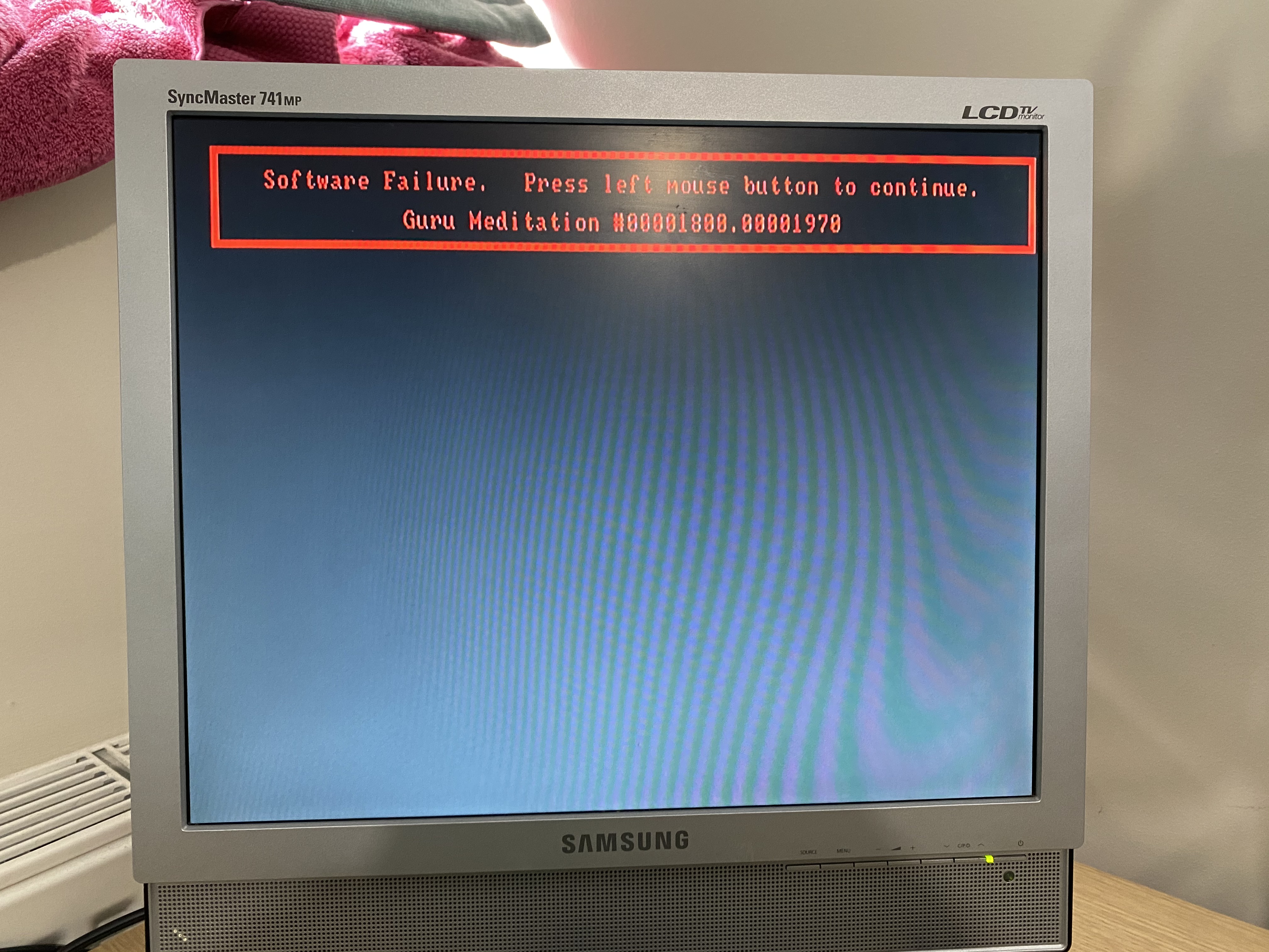
The symptoms were that it would rarely reboot when attempted. Both software reboots (from the Gotek’s software) as well as Ctrl-Amiga-Amiga failed, either with a hang or the reboot doesn’t complete. Occasionally I just got a black screen when powered on. I would also sometimes get random Guru Meditation errors immediately on reboot.
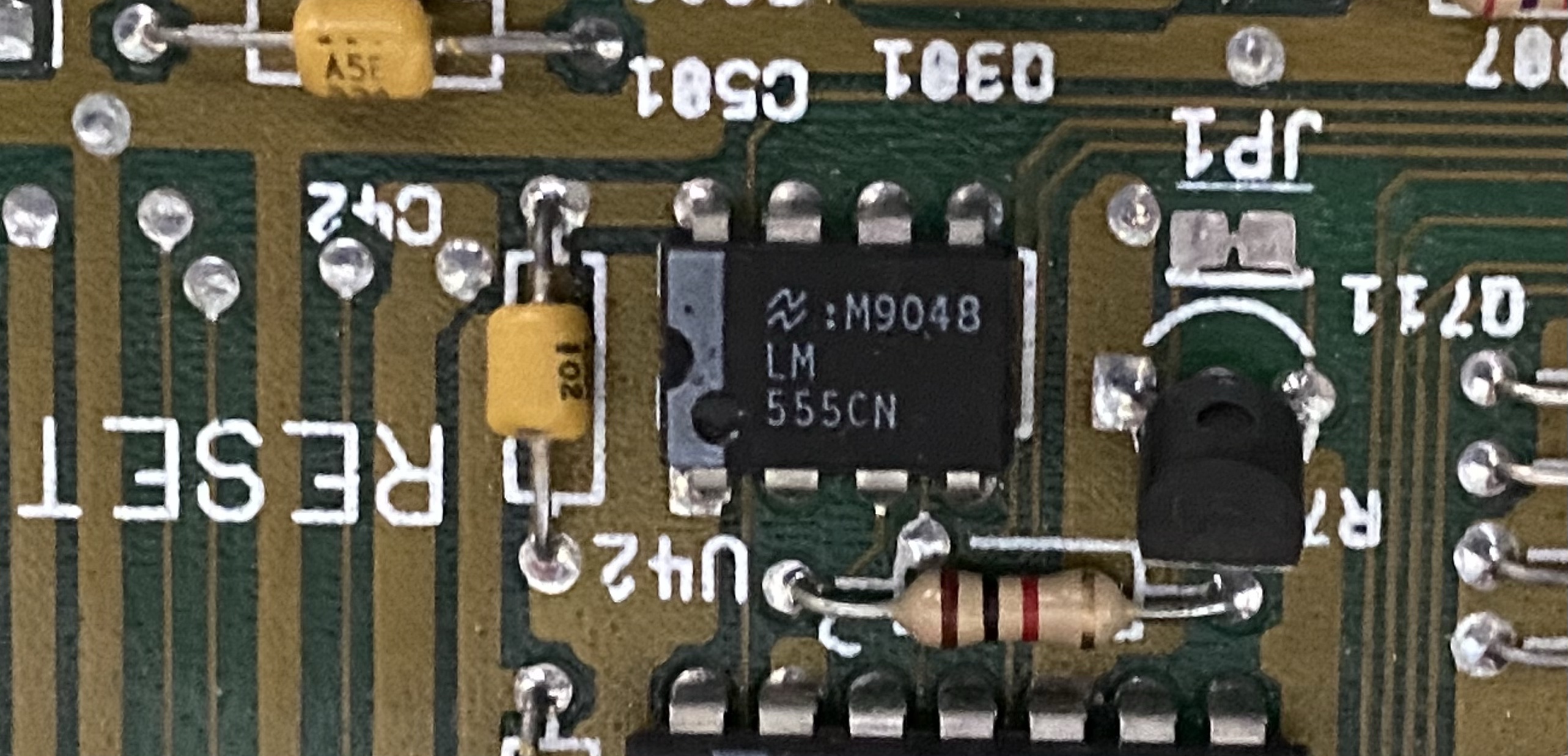
Amiga reboots are actually really simple and really clever. If you have ever done a basic electronics course you will be familiar with the 555 timer. This is a basic chip which can flip from one state to another using timings determined by passive components (resistors and capacitors). The Amiga actually has 2 of these, one in the keyboard controller board and one on the main PCB. For the main PCB one the sole job of this is to reset everything around 100ms after the machine is turned on.
In the Amiga 500 Ctrl-Amiga-Amiga is caught by the keyboard controller and sends a physical reset to the motherboard. This actually is the same physical PCB trace as the 555.
Now, I knew the circuit around the 555 wasn’t the culprit because it was often booting and Ctrl-Amiga-Amiga was definitely firing the reboot but it never completed. Worst case for a bad 555 circuit I would see repeating reset signals. But probing the output showed it was working just fine.
I have a chip called a DiagROM which is a nifty ROM you can burn yourself that replaces the Kickstart boot ROM and runs a barrage of diagnostic tests on the board. It can even give you readouts with a null modem cable if there is display issues (I don’t actually have one of these cables yet).
I plugged in this chip and all I got were random colour screens. Different every time I booted and rebooted. Each indicating different things but they all appeared to be red herrings.
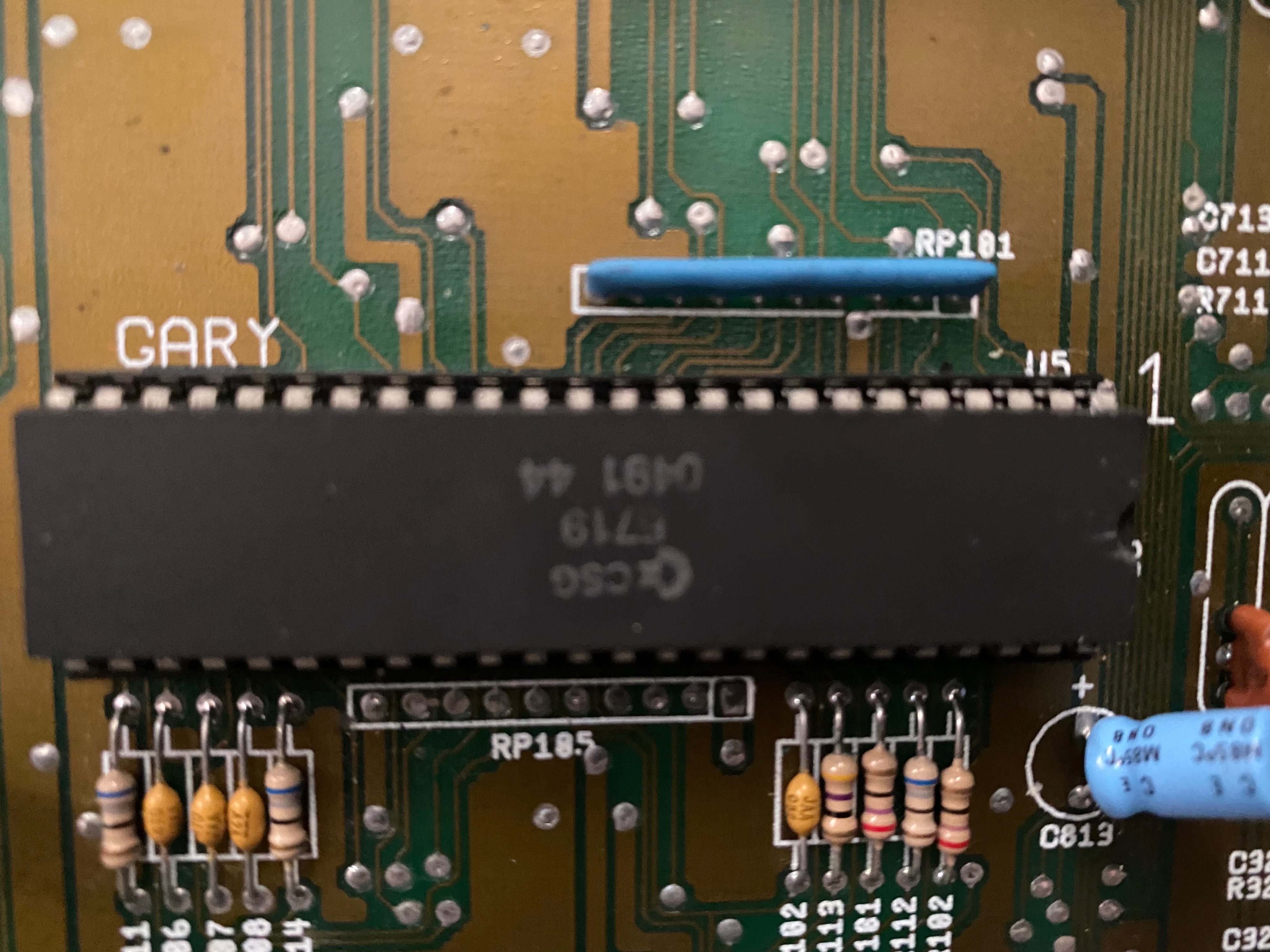
So, back to the reset circuit. The input from the 555 and keyboard goes into a chip called Gary (short for Gate Array). This then fires the HLT and RST lines for all the other chips. I figured Gary may be bad so I swapped out this chip for a known good one, as well as the CPU for good measure. No joy.
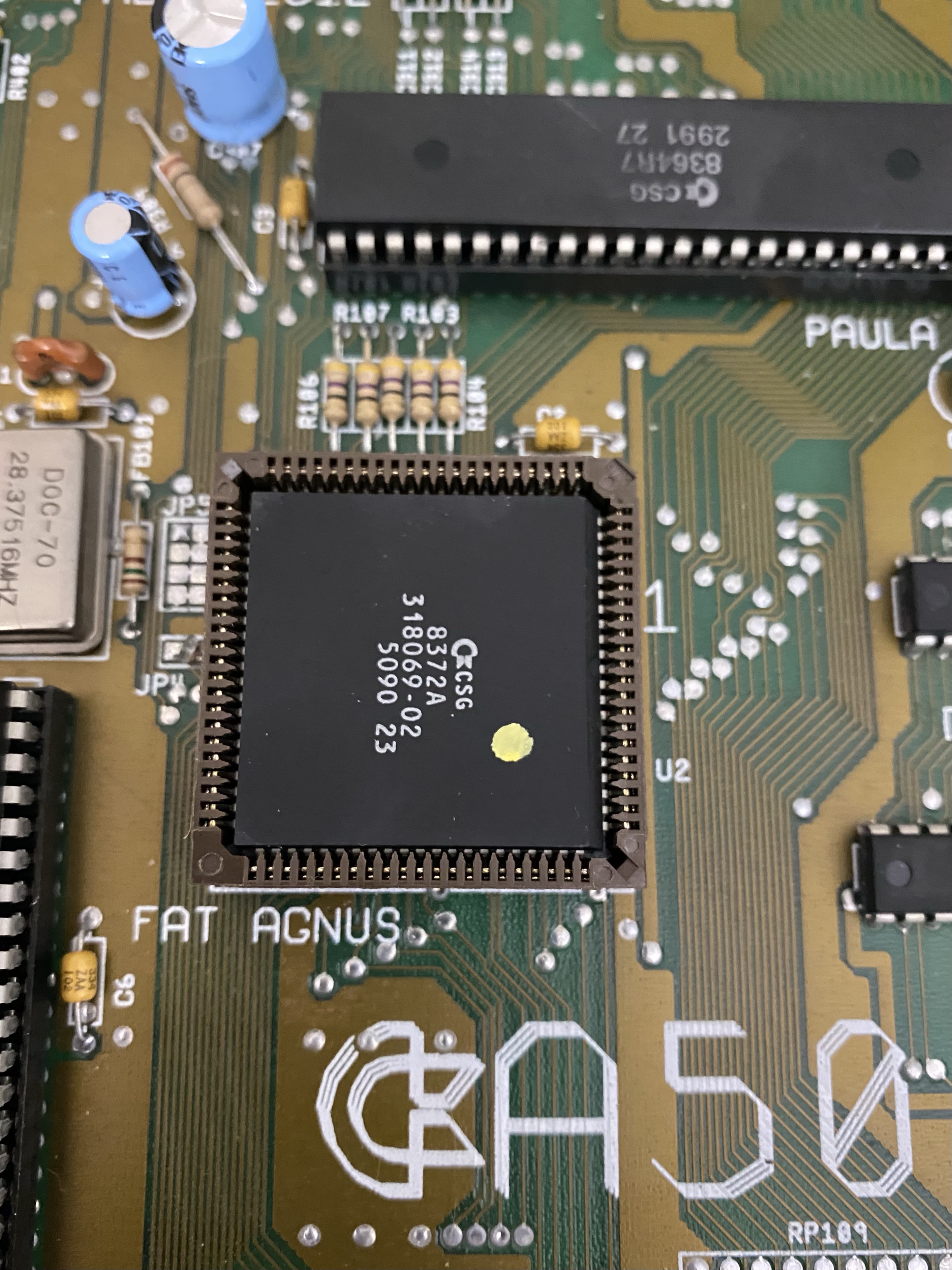
I was a little worried that it may be the Fat Agnus (Address Generator Chip) that is bad, which would not be good because I don’t have a spare of that version, it is expensive to replace and more often than not the 30 years old socket breaks when pulling it.
I decided to test every part of the reset circuit. The pull up resistors and all the traces. When I got to buzzing the circuit to make sure HLT and RST were reaching the CPU I found HLT was fine, but there was no connection for RST between Gary and the CPU. Bingo!
I followed the trace for this and found that it goes directly under R402 which I replaced earlier due to some corrosion that had eaten away at it. It turns out that the same corrosion had damaged the trace under the resistor.
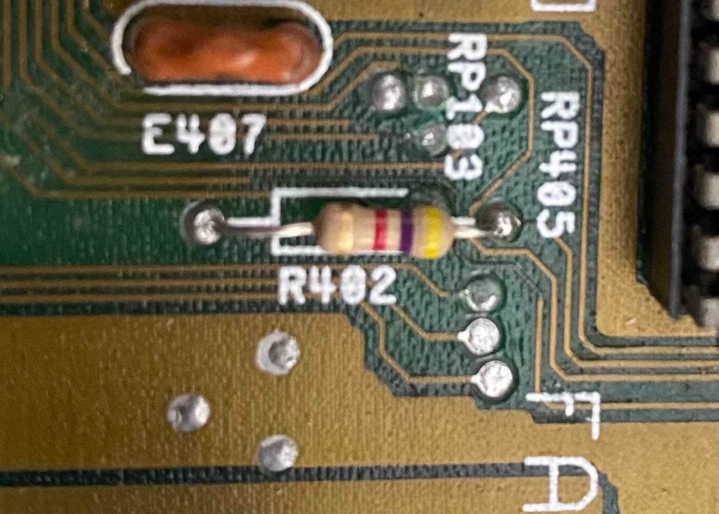
I could have maybe repaired this by removing the resistor again, scraping off the silk screen and using a conductive pen to redraw the trace. But instead I decided to add a small wire.
The temporary fix was to join the RST line going into Paula (which was closer to the CPU than Gary) to the CPU by literally shoving a wire into the socket with the pins. This worked perfectly. I had the machine running for about half an hour, doing multiple power ups and reboots. I even ran lemmings on it for good measure.
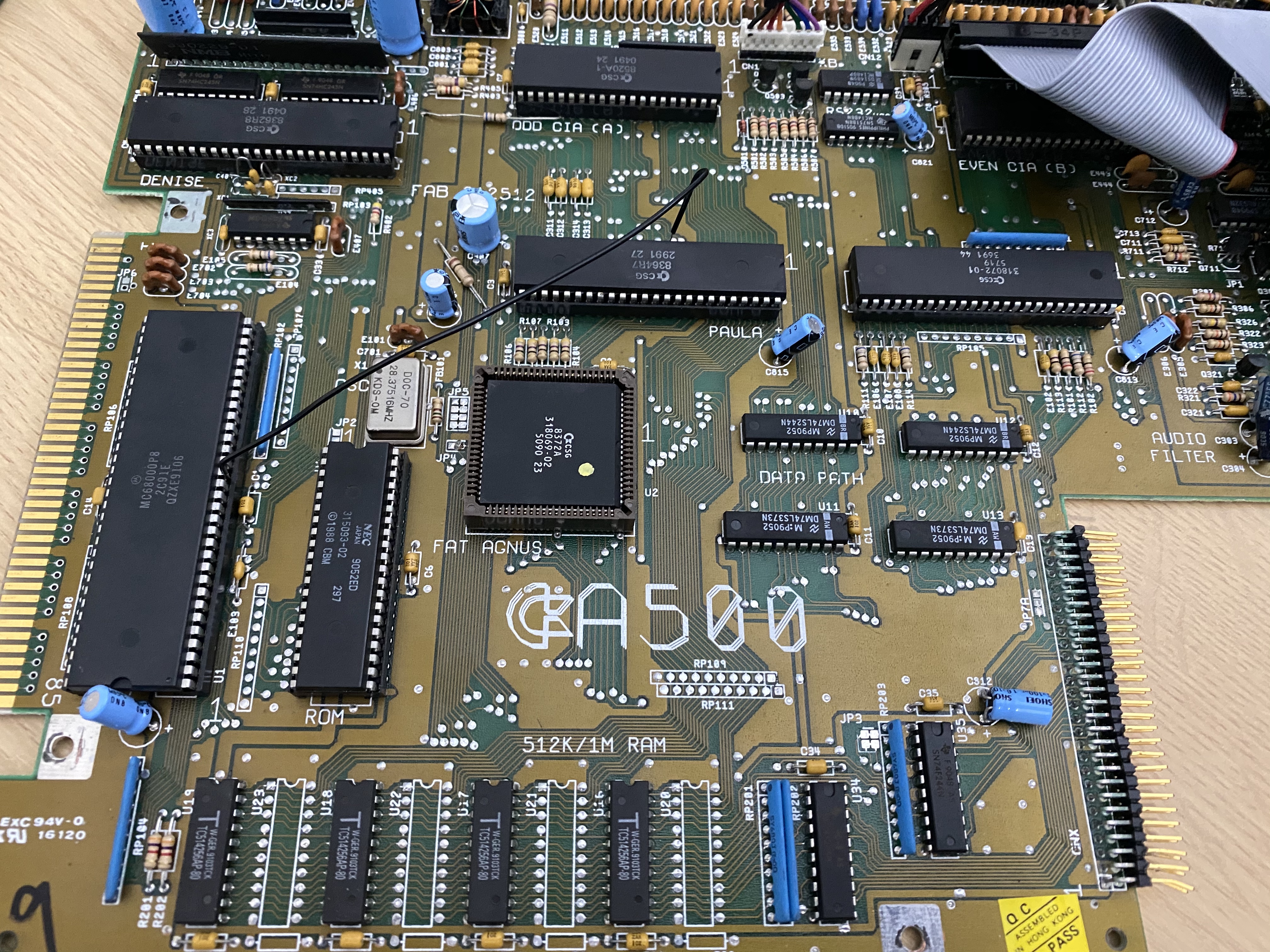
To make this fix more permanent, on the CPU side there is an expansion edge connector which also gets the RST line, and there is a neat through-hole here I could use. On the Gary side I used a pad for the RST line under the resistor where the breakage is.
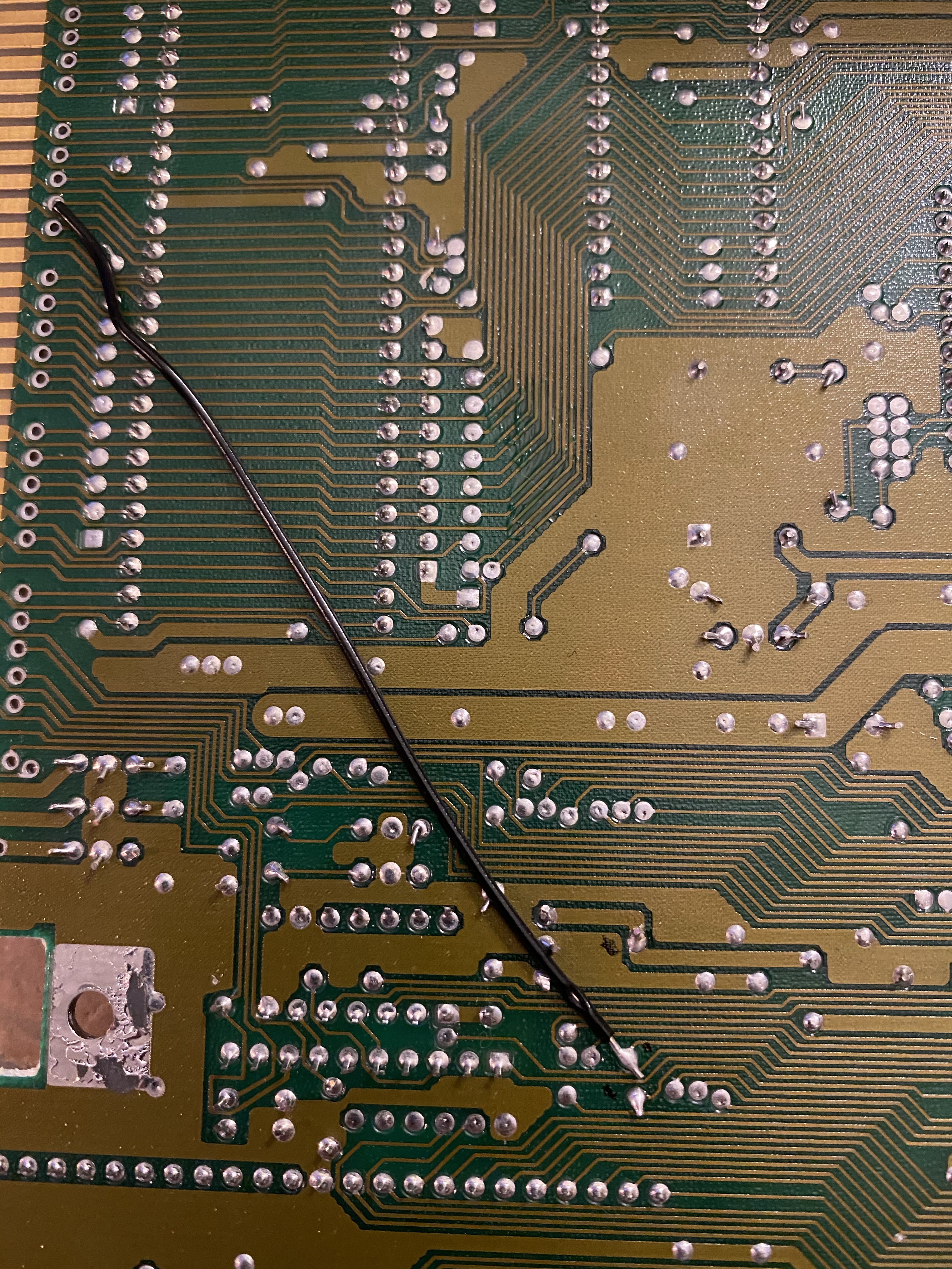
Job done! Logically this Amiga is all fine. I still need to replace a damaged trap-door connector. But I’m waiting for a replacement to come before I attempt that.
Leave a Reply