

For some upcoming projects I need to have a working CAN bus to play with. On one end I have my Linux laptop with a USB CAN bus module. On the other end I bought a cheap module which claimed to be Raspberry Pi compatible. It turns out that it needs a little tweak first.
Initial Problem
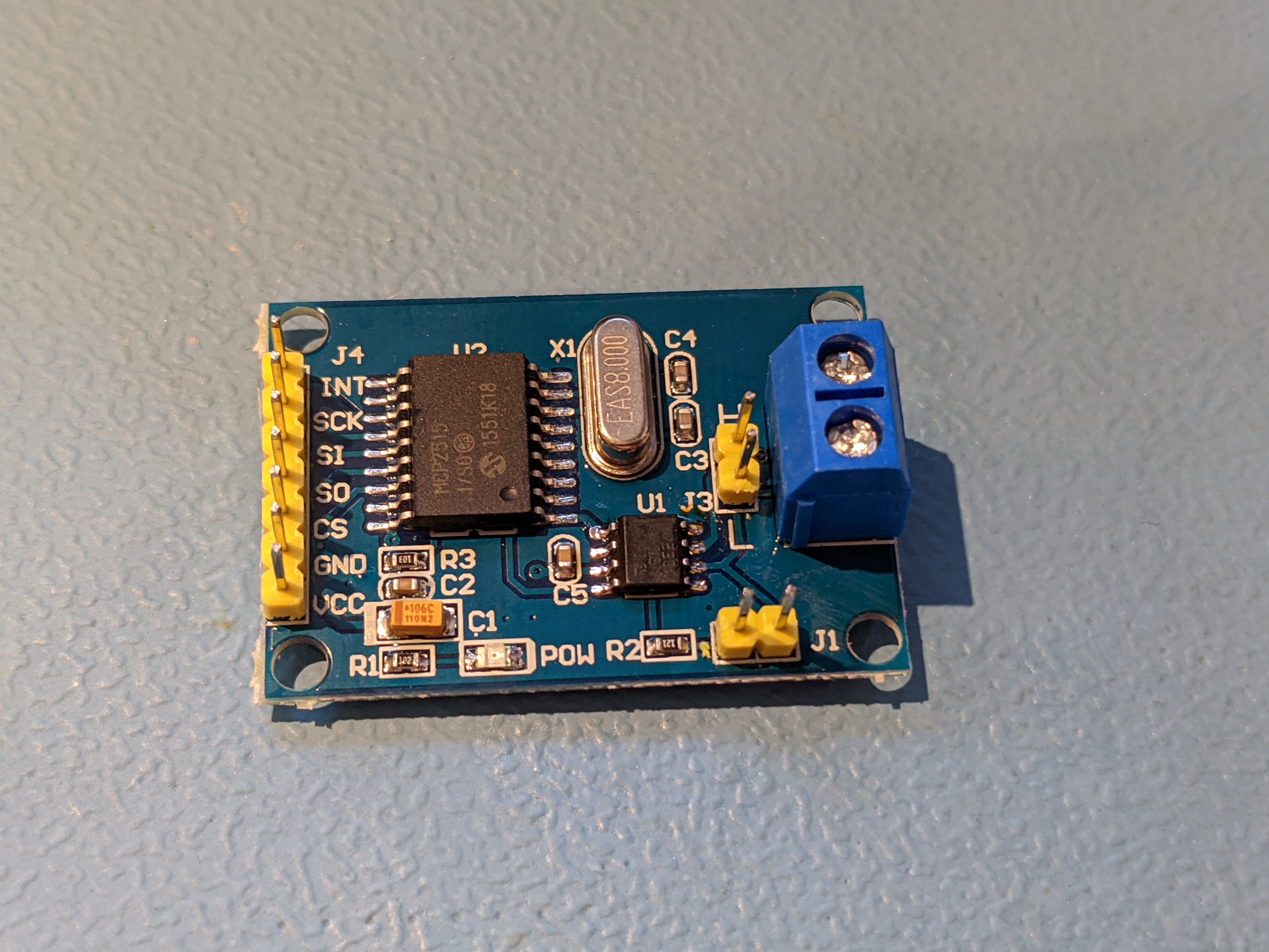
The module in question is this one from Amazon. It is also available at AliExpress and several other places. It uses an MCP2515 to provide an SPI interface and a TJA1050 as the CAN bus transceiver. The problem is with this second chip.
The Raspberry Pi’s GPIO only works at 3.3V, if you provide 5V to any of the GPIO pins, that will fry that pin inside the Pi’s processor. It is the cause of pain to many a Raspberry Pi users and I wish that Raspberry Pis would have buffers between the GPIO and IC so that they can be repaired. I myself have two Raspberry Pis with cooked GPIOs but are otherwise functional.
Now, the TJA1050 only operates at 5V, if you supply it 5V then you have to supply the whole board 5V (unless you modify the board) and that means that 5V is returned to the GPIO pins. Which is a bad thing.
There are a couple of workarounds, the first is to cut the power trace to the MCP2515 and supply 3.3V to that separate to the 5V of the TJA1050. In my case I decided to take another path, replace the chip with a 3.3V compatible one. The SN65HVD230 is pin-compatible with the TJA1050 and works at 3.3V.
Replacing the Chip
The first step is to remove the TJA1050. I protected a few things with some kapton tape, put some Amtech flux around the pins of the chip and used my Quick 861DW and some tweezers to remove it. This only took about 10 seconds.
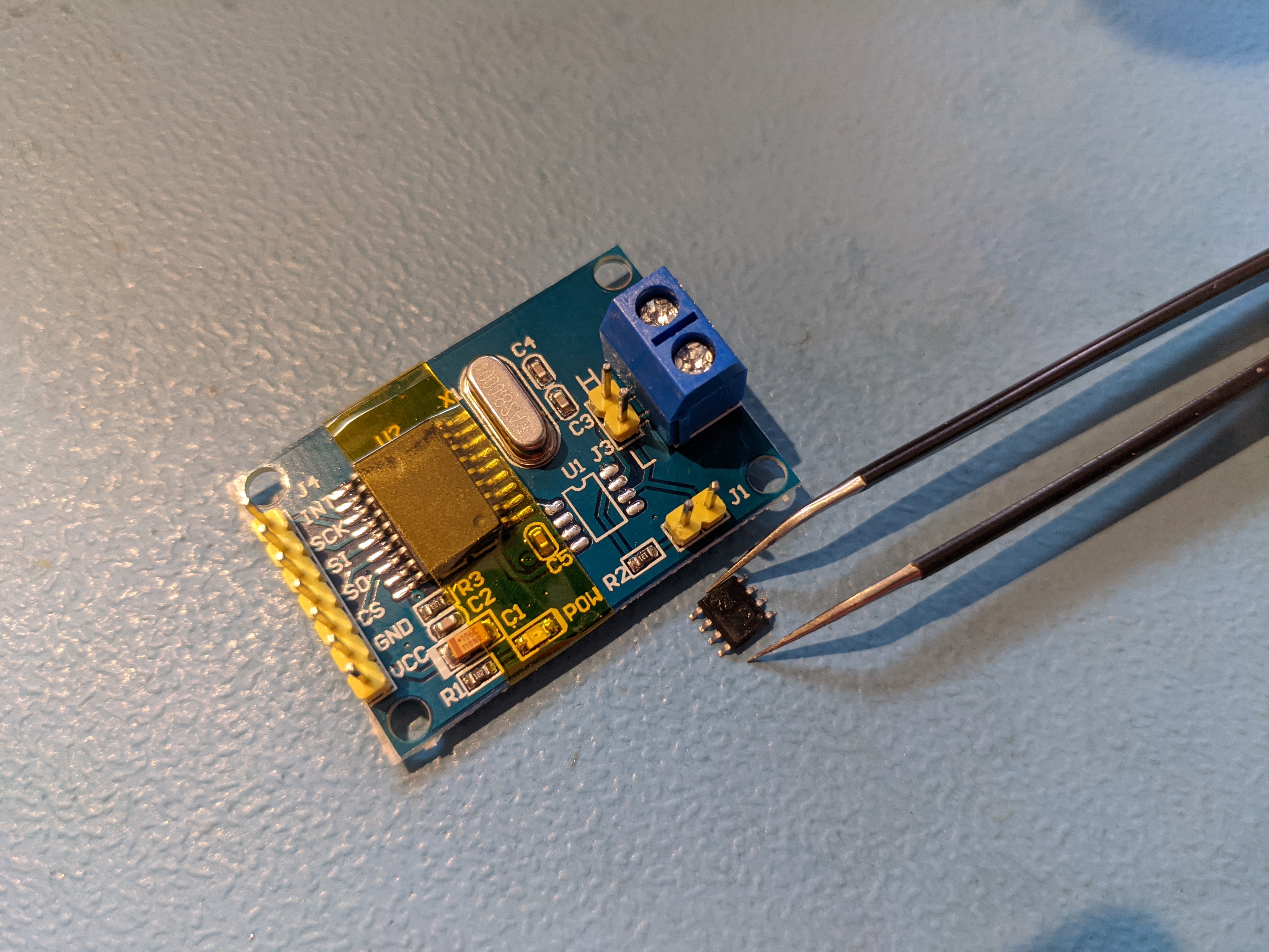
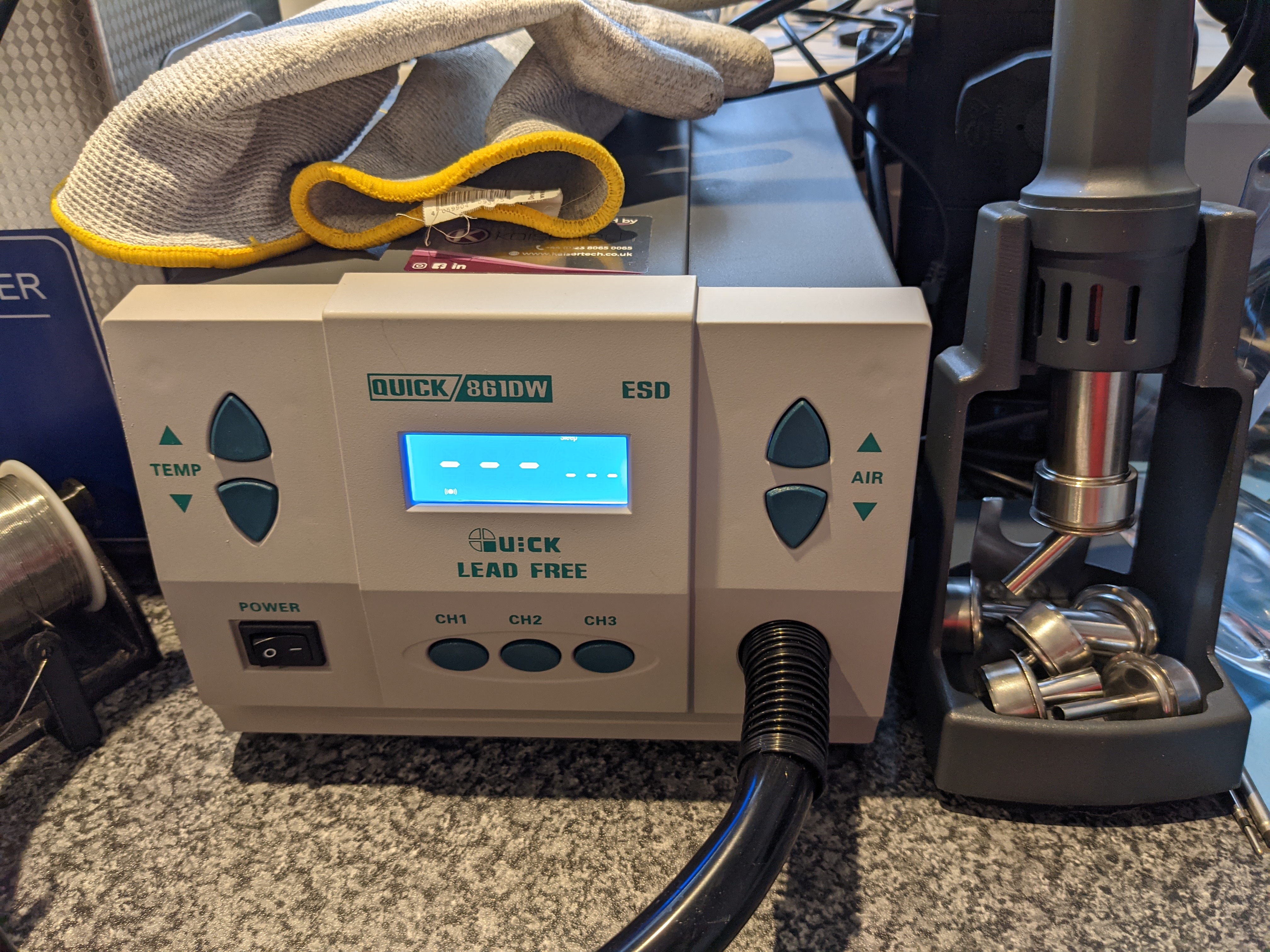
I highly recommend the 861DW over cheaper hot air guns out there, it is much better at transferring the heat and some of the more budget models have been known to fail high, catching on fire, when the fan fails.
It was then a case of using some soldering braid to clean the old solder off the pads and soldering on the new chip. I used my very old microscope (which has fantastic optics) and my JBC CD-2BB soldering station with a 1.9mm spoon tip (C245-965) with some Amtech flux and 0.5mm solder to drag solder the new chip in place.
Wiring to the Pi
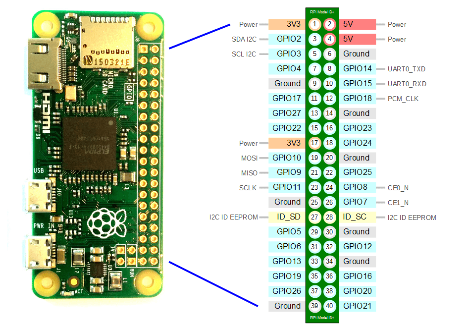
Now we have the hardware we need to wire it up. This is done using the following:
| GPIO Pin Number | Connected To |
|---|---|
| 17 (or any 3V3 pin) | VCC |
| 19 | SI |
| 20 | GND |
| 21 | SO |
| 22 | INT |
| 23 | SCK |
| 24 | CS |
Software Setup
For this I have used Rasbian Lite as standard. I use this headless (no monitor or keyboard) so, prior to first boot I made a few changes. First of all, editing config.txt in the “boot” partition to enable the CAN bus driver. Add this line at the end of the file:
dtoverlay=mcp2515-can0,oscillator=8000000,interrupt=25
I also want SSH to be enabled on first boot, this is done by creating a blank file called “ssh” in the “boot” partition, in Linux and macOS you can just do it by using touch ssh. Finally I setup WiFi so I can use SSH to talk to it by creating a file called wpa_supplicant.conf in the “boot” partition with the following contents (note that the SSID and psk values are case sensitive):
ctrl_interface=DIR=/var/run/wpa_supplicant GROUP=netdev
network={
    ssid="YOUR_SSID"
    psk="YOUR_WIFI_PASSWORD"
    key_mgmt=WPA-PSK
}
The first boot will take a couple of minutes because it needs to resize the root partition. You should then be able to SSH into it.
Starting the CAN Bus
You can check to see if the driver worked by executing dmesg | grep can0, you should then see:
[ 10.918782] mcp251x spi0.0 can0: MCP2515 successfully initialized.
From here you can start the CAN bus a little like connecting to a network, this sets things up at 500kbit:
sudo /sbin/ip link set can0 up type can bitrate 500000
Testing
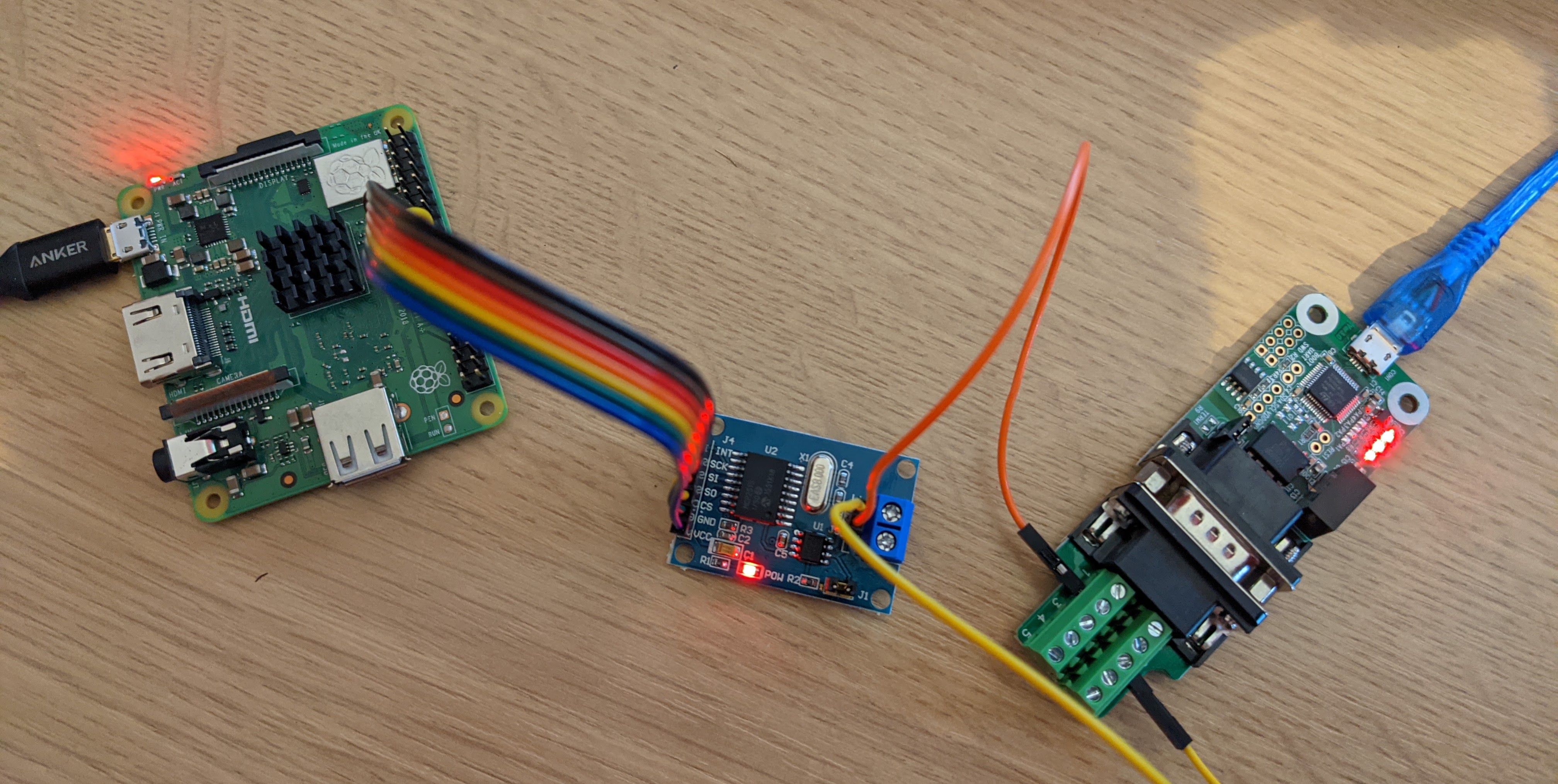
You can see from my hardware setup below that I have a Raspberry Pi 3A+ with this board and I’m using a USB CAN bus board to connect to my laptop. The terminator jumpers are on each as both are the ends of the cable. The wires technically should be twisted together but for this distance and speed it doesn’t really matter too much. The important thing is the wires are the same length.
On both ends I’ve installed can-utils using:
sudo apt install can-utils
Then on the Pi I ran the following to dump out all bus transactions to STDOUT:
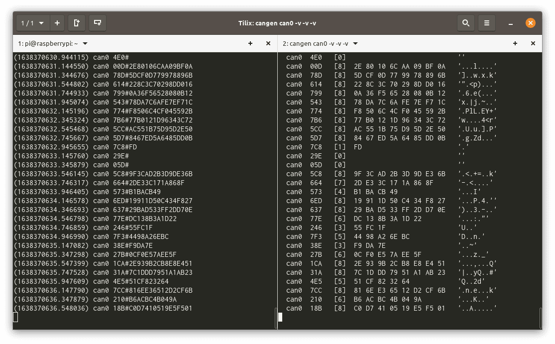
candump -L any,0:0,#FFFFFFFF
On my laptop I generate random traffic using:
cangen can0 -v -v -v
This creates the following output (left is the Raspberry Pi, right is my laptop):
Leave a Reply