

I recently upgraded a friend’s TF534 to have a 68882 FPU in it, a simple case of soldering a PLCC socket onto the board and popping in the chip. When that was delivered for the upgrade, in the box was also a c0pperdragon Amiga v2 board that was badly damaged. I said I would have a go at repairing it.
The c0pperdragon is set of boards for various retro machines that hook their video output signals into a Raspberry Pi Zero. The Pi then emits a very low latency (a few ms) crisp HDMI output of the signal. This is probably as pixel-perfect as you can get for an HDMI output of a 30 year old machine without emulation.
There is a small board for the Amiga for this which sits under the Denise video chip and pulls the RGB data from the pins there. Version 2.0 supports both the original Denise and the Super Denise in the Amiga 500 Plus, part of what is known as the ECS chipset. As per the GitHub page, it should look like this:
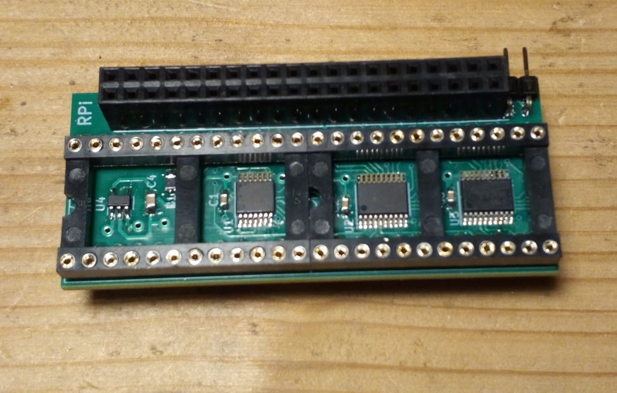
Denise sits on the chip socket there, there are pins underneath to go into the Denise socket and the Raspberry Pi goes into the header at the top.
My friend ordered one from the board’s designed, and unfortunately it was not packaged well, it arrived to him into the UK looking like this:
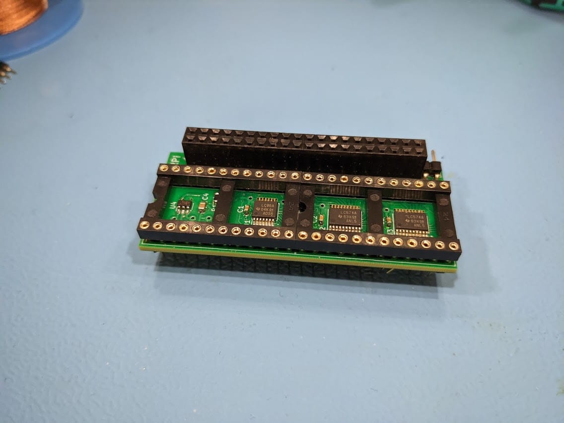
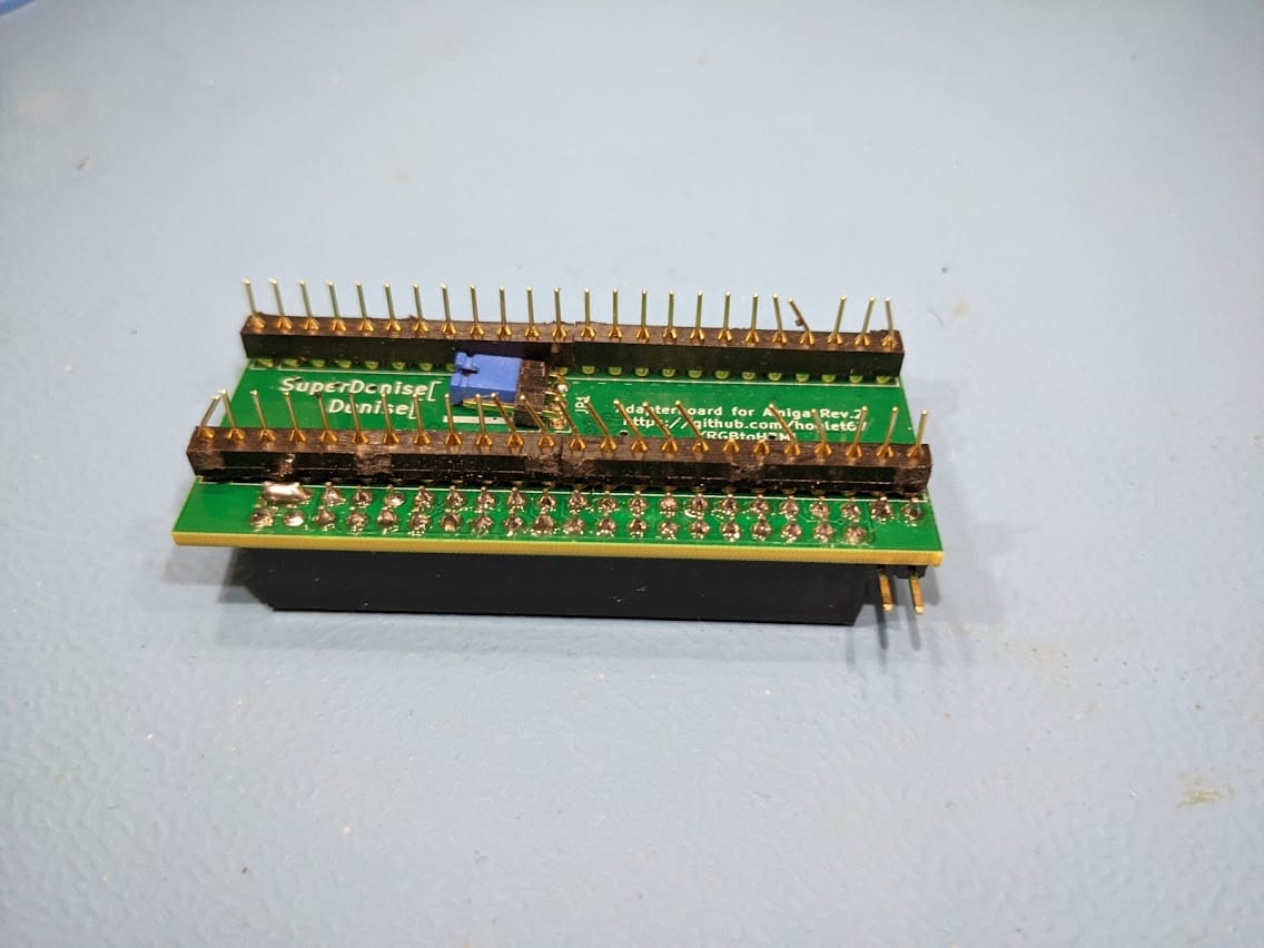
Whilst the first image isn’t a problem, the second image definitely is. Many of the pins were bent, some of them were snapped off, several more just fell off during light handling of it. As a side note, whenever you post something electronic with pins, please make sure the pins are protected.
Now, unfortunately due to the configuration of the board I needed to get the Denise socket off the top of the board to expose the solder joints for the pins underneath. Even more unfortunate is that everything is so close together on the board I couldn’t use my desoldering gun without melting a lot of plastic. But as luck would have it, I had one socket left of the right size and had several strips of pins to go underneath.
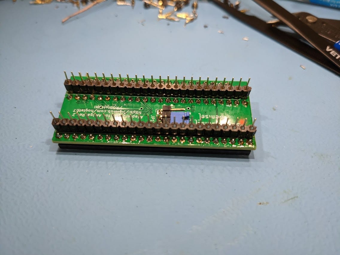
I used solder braid to desolder the joings and a ended up cutting away the plastic so I could easily remove and cleanup pin-by-pin for both the socket and the rows of pins. This probably took a couple of hours and I did damage one pad in the process which I managed to repair with a tiny hidden through-hole wire between the socket and the pins.
The end result looked like this:
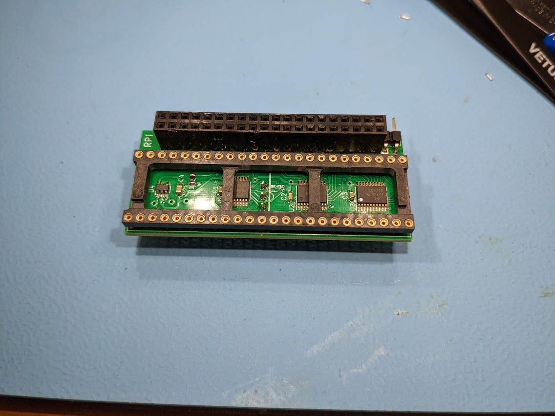
It might have been quicker in terms of soldering time for me to just make a new one as the board is quite simple as far as SMD work goes, but it saves having to throw the original away. Also, it would take several days to get PCBs, components, etc… It would probably only be worth it if I was making 10 or so of them at least.
After I had repaired it I had to test it. My rev. 6 Amiga 500 test board only has a regular Denise so I switched the jumper at the bottom to this mode and hooked everything up.
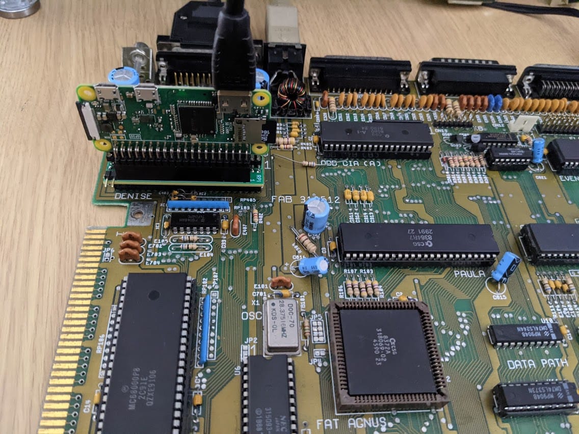
My Raspberry Pi Zero is normally used for Xilinx programming so I have the header at a 90° angle. Normally the Pi would sit flat with the Pi’s HDMI and USB connectors closest to the Amiga’s CPU. The software for the Pi is available from another GitHub repository. You can just download the zip file from the releases and extract it onto a FAT32 formatted Micro SD card.
Then it is a case of just turning on the Amiga. The HDMI output takes a few seconds to bring up as the Pi boots, powered by the Amiga itself, and you can still use the regular RGB output of the Amiga at the same time.
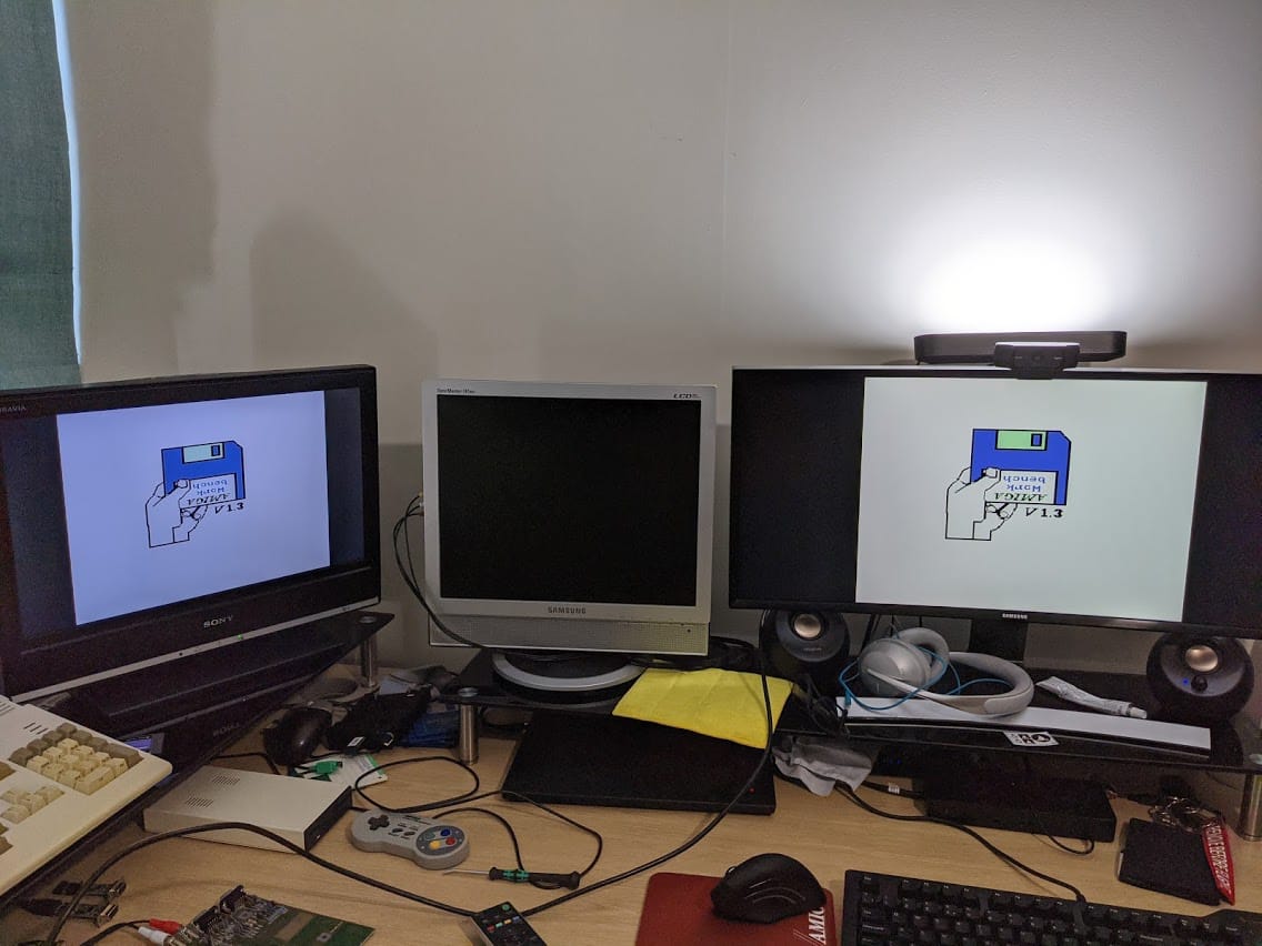
You can see below the state of my messy desk on a Sunday morning, but also the board and software at work. The left screen is connected to the original Amiga video port using a scart cable. The right is connected to the Pi via HDMI.
So, it seems to be all good now. I will carefully package this up for its owner to play with.
Leave a Reply