

Karl at Retro32 likes to challenge me, and this time he had an interesting one. When he turned on an Amiga 600 motherboard he acquired, smoke and a small flame came out of the motherboard!
The motherboard
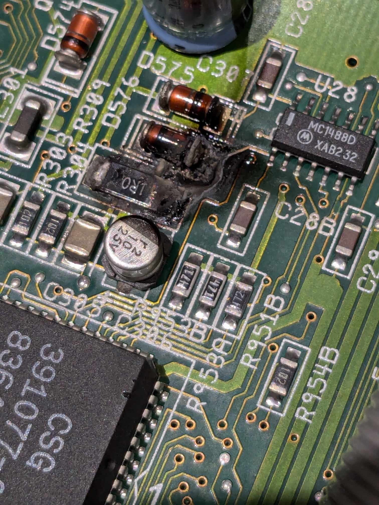
When Karl contacted me about the motherboard, these are the photos I was sent:


From this, I immediately had a good idea what had happened. Karl confirmed with a multimeter that there was a dead short between 5v and GND.
What happened
My theory was as follows:
The key is resistor R304, which is a large 1 ohm resistor. This supplies power to Paula from the 5v line. Running under this resistor is a large GND plane. The electrolytic capacitor next to it had leaked, the corrosion of which had caused the short circuit between the 5v input of the resistor and GND. There was likely a minimum of 12W of power going to that short, which caused extreme heat.
A potential -12v to GND short was also possible via the diode that also looks burnt.
Analysis
Once the motherboard had arrived on my desk, I removed the capacitor nearby to get a better view and cleaned a bit, so I could check out the damage. You can see the burn there, it might not be too obvious from the first photo, but there is a crater about half the depth of the motherboard. Melted material had leaked through the vias to the bottom, and it had even slightly burnt the plastic protection sheet under the motherboard. In addition, the IDE port was badly corroded.


I removed the resistor and diode, which wasn’t too difficult because there was a crater where the right hand pads used to be.

You can see some of the GND plane copper in the middle of the footprints there. As expected, the charred remains to the right were conductive, causing the 5v – GND short.
I cleaned up the area and dug the conductive charred material out. This was starting to look better, and the 5v – GND short had disappeared.

I knew Paula wouldn’t work because the resistor supplies power to it, so I would not get Kickstart to boot. But, DiagROM should work without Paula. Unfortunately, I wouldn’t get a serial diagnostic data out either, the missing diode supplies -12v to the serial port IC. But, it was worth a shot.

It booted! That tells me a lot. Most of the chipset works, the RAM at least initially works. The one thing I can’t test is Paula.
Repair
I used a clear protective coating to cover the exposed GND copper and soldered replacements for the two components. The old ones tested OK, but I figured their life would have been drastically reduced.

In theory, I could now put the original Kickstart ROM back in and test it. I did so and it booted.

I then worked on recapping the motherboard. This took a lot longer than normal. Every electrolytic SMD capacitor had leaked. I had to removed tarnish and burnt electrolyte with every capacitor I removed. The smell was awful and filled the entire workshop.
Eventually, I completed this, and whilst I was at it, I replaced the IDE connector with a brand new one. Karl requested that I remove the TV modulator whilst I was desoldering, so I did this, it also means 4 capacitors used for the modulator are no longer needed.

I ran the board through a battery of tests, unfortunately there was no right audio, but fixing that was just a small patch where the capacitor corrosion had damaged the trace to a pad for the right audio port. A quick patch fixed that.

And that is it! One complete working motherboard ready to go back.
Conclusion
There are some that claim that preventative recapping of SMD caps in vintage computers is not needed. I hope this shows that it is always a good idea, even if the machine appears to work.
Leave a Reply