
In my previous post, I introduced two Amiga 4000s I received from Stoo Cambridge to repair. Since then, I have been working on the motherboard of Jools. Let’s see how far I got…
RAM repair
You may recall that I named the two machines Jools and Jops, and that for now, I’m focused on getting Jools running.
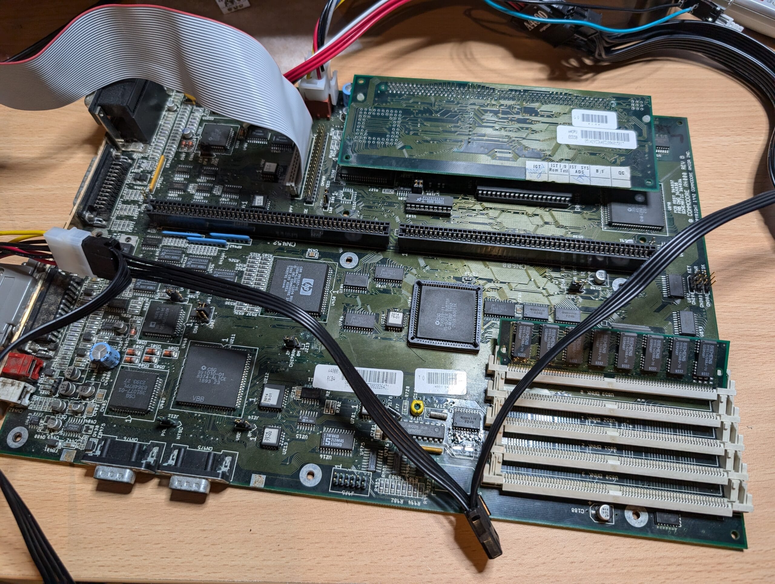
I mentioned that I suspected that the GND pin on U891 was not attached. This is important because if this chip is not powered correctly, it completely pins the data bus for the system, and it will not boot.
The first thing I did was repair the wiring of the pin, it is difficult to see, but there is a thin dark blue patch wire going from pin 10 of the chip into the via. This is attached to a ground point on the bottom of the board.
This doesn’t look great right now, I just wanted to get it functional before I cleaned it up further. I removed C192, in part to give myself some space, but also because it needs replacing anyway.

Now, in theory, if there is no more damage, the machine will boot with Chip RAM only. So, I set up a rig to test this. The photo below is from me doing this before I did all of the clean-up above.
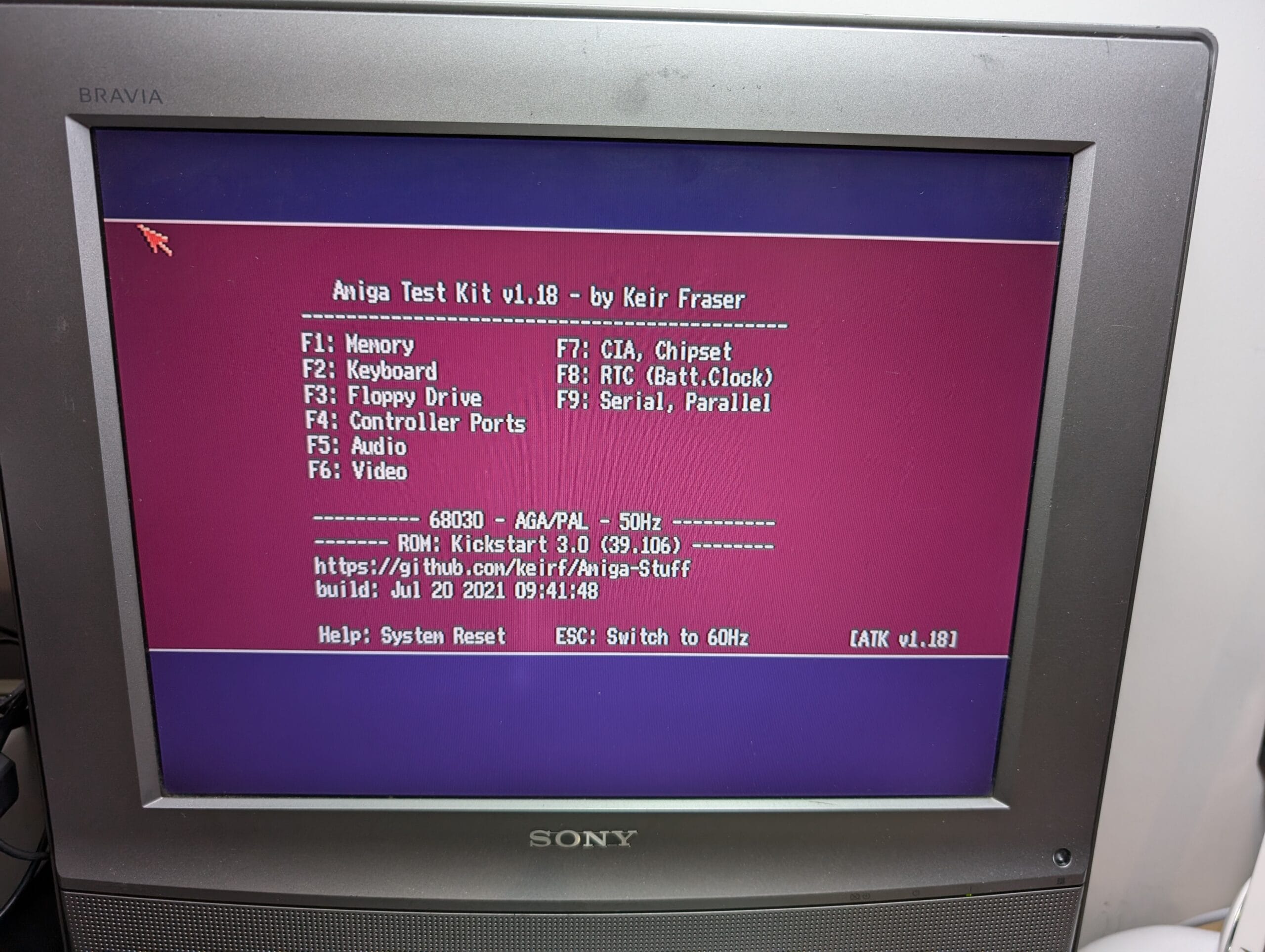
Excellent! Things become much easier once it is booting from Kickstart. There is still more work to do, but from here, we can diagnose further.
Audio works, Chip RAM works, chipset is all good. The RTC wasn’t detected.
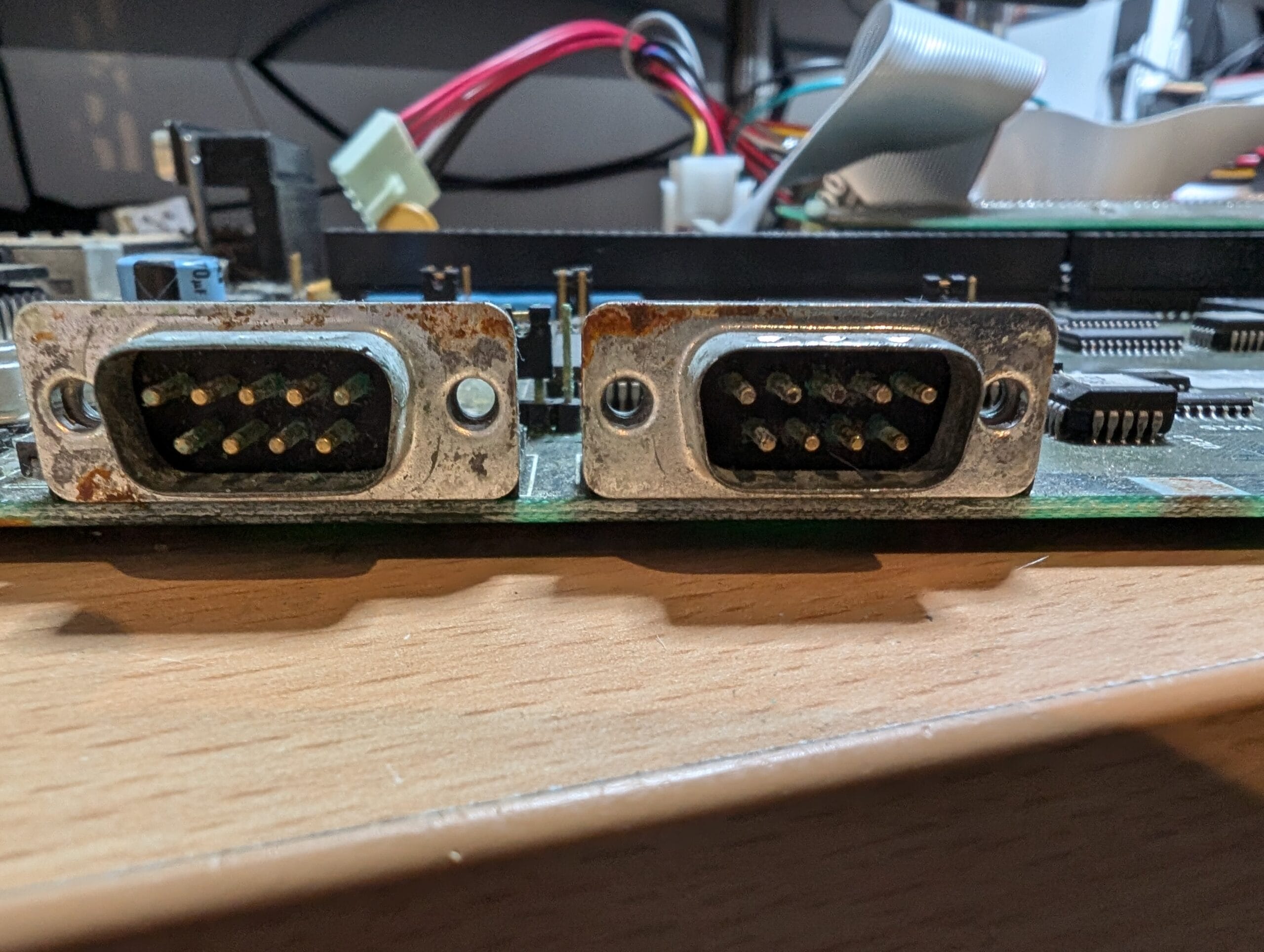
I also cleaned enough of the corrosion out of the joystick / mouse ports to test them with a sacrificial old joystick. Everything works there, but they will be changed in the end.
More cleaning
Before I diagnose further, I need to do a bit more clean-up. So, in the photo below I have:
- Cleaned out the solder and crud from the vias on the battery side of U891
- Cleaned up the soldering of U891
- Cleaned out the solder and left over pins for the battery holes
- Removed U177 and cleaned up that area so that I could assess the damage there. I will put a new chip in its place due to the corrosion
- R993 had a broken +5v trace, this was repaired (off photo)
- Repaired D0 to the bottom SIMM socket (under the board)

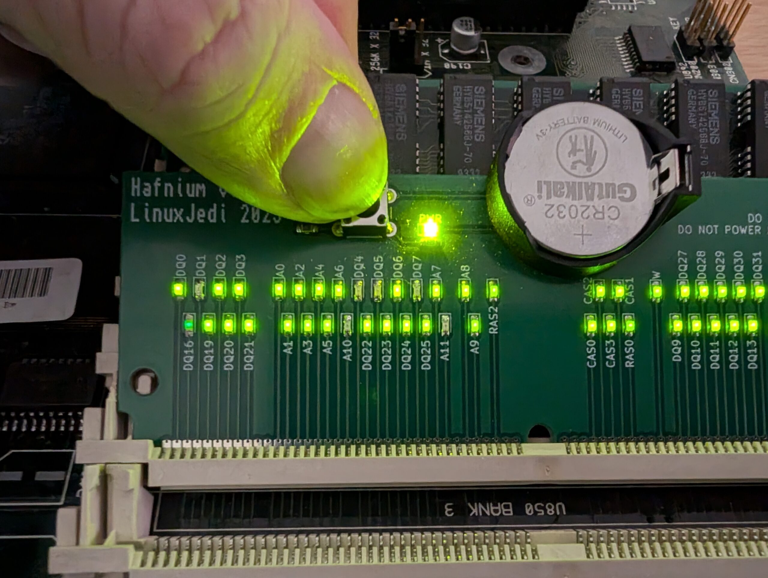
This led to me to probe and find out everything else that is broken. First with Hafnium again, then with a continuity tester.
Broken traces
We can see Hafnium is now showing D1, D4, D5 and D7 is broken. We don’t need to worry about A10 and A11, they are not connected on an Amiga 4000. The following from AmigaPCB.org shows where these are hooked up.

I checked all of these with a continuity probe, they are all broken between U891 and the via holes right next to them. Which means they should be relatively easy to fix.
Next up the RTC, probing around I found the following traces are broken.

That is not unexpected, it is the closest chip to the battery, so it often gets hit hard.
Other fixes
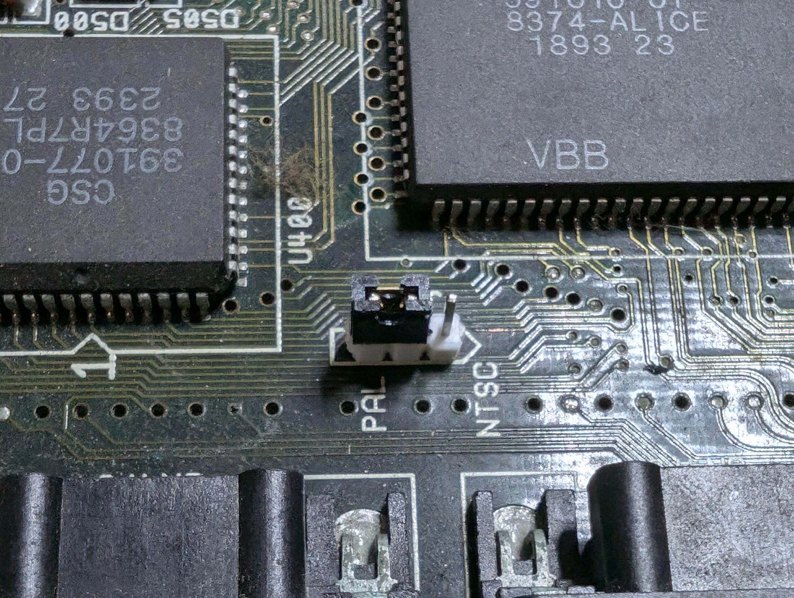
The J975 header was very green, as was the PAL/NTSC jumper. The header is not used for anything, it was intended for an expansion that was never completed. Therefore, I have completely removed it.
The jumper pins and jumper itself were replaced. Unfortunately, I only had white or yellow pins available. So, I have used white for now.

Next steps
I’m going to repair and test the RAM area next, then the RTC. For the RTC I’ll likely desolder the resistor pack next to the RTC and use it to hide much of the repair. I have a new chip for U177 to put in place of the old one.
Then, for now, it will be a case of testing the PSU and reassembling. It will come back to me at a later date to have the SIMM sockets replaced, and the new owner will be replacing the joystick/mouse ports himself.
Look out for future posts in this series!
Leave a Reply