In my previous post, I had the Amiga 4000 known as Jools mostly repaired, there were still a couple more issues found after the board was cleaned. So, let’s get into part 4 of this series!
More RAM repairs
I had found that there was a PCB trace for the RAM which was fractured, flexing the board would break and fix it. I patched this, but the Fast RAM was still not being detected, which was concerning. Using the RAM from my own Amiga 4000 was not helping. Hafnium was showing that all is good now, but the motherboard wasn’t seeing it.
I booted DiagROM to see what this made of it, it also could not detect the RAM. Which meant more drastic action should be taken. DiagROM has a memory editor, with which you can write and read back RAM data. Using this, I jumped to the Fast RAM area of the memory map and filled a line of it with 0xAA.
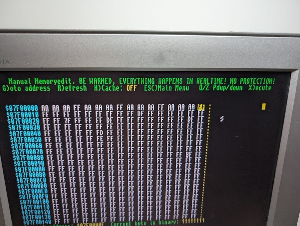
Now this is interesting, data in the low 8bits of every 32bit block was either not being written, or not being read.
It is actually quite easy to diagnose this. Remember U891? Not only does it buffer the signals to the low 8bits of the data bus, but pin 1 tells it which direction to work in. That makes it essentially a read/write switch. As expected, this was broken. Likely close to failure and the ultrasonic cleaning caused it to break when removing corrosion.
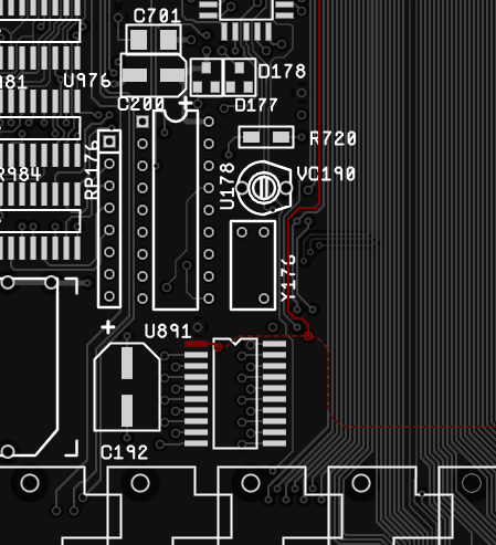
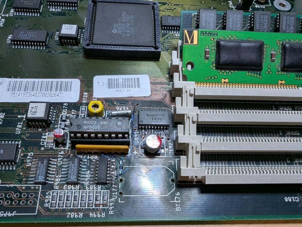
Another patch wire added, and…
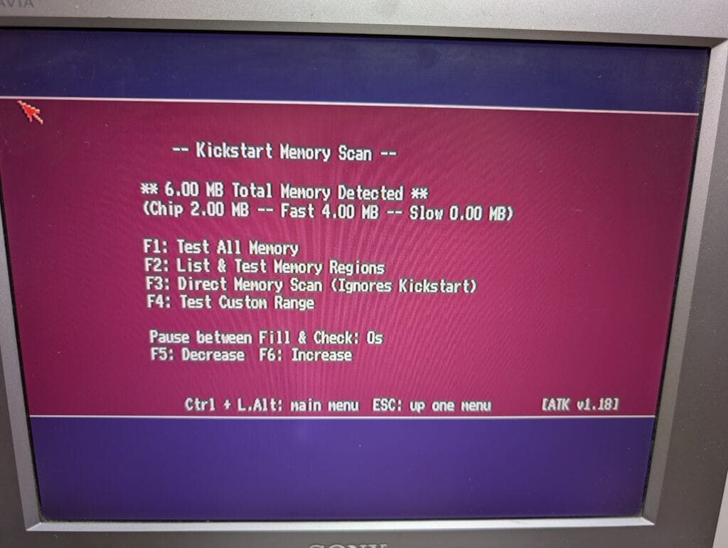
All the RAM can be detected again!
RTC fix
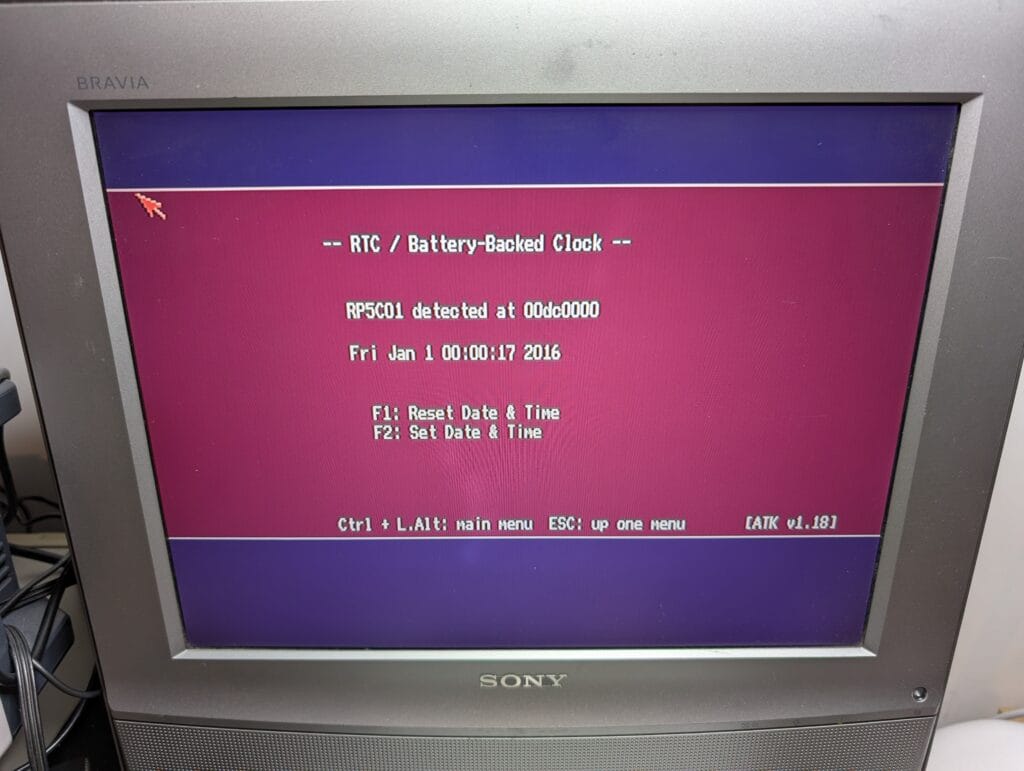
I also mentioned last that the RTC was running very fast, it was running at roughly 2x speed, it occasionally jumped a second backwards too, which was a bit weird. I probed the crystal with a frequency counter, it was spot on at 32,768KHz.
In the end, I decided to swap out the RTC chip (I’m glad I socketed it now), this immediately resolved the issue. Obviously, this is a photo, not a video, so just imagine this incrementing once a second 😊
Final testing
The one thing I haven’t tested yet is the IDE connector. I was pretty confident it was going to work, but best be sure. I connected up my Kickstart 2.0 test CF card. It immediately booted.
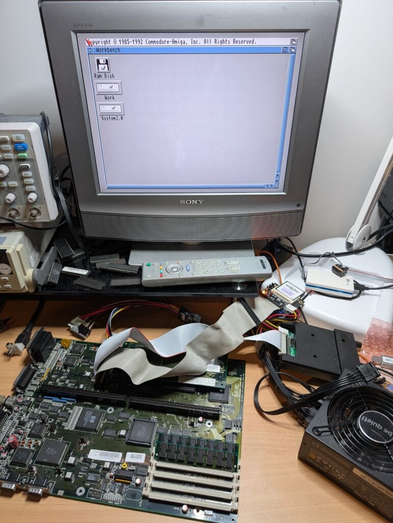
There is a minor issue, however. There is a chip that is half tucked under the SIMM socket closest to the edge of the board. This is a basic 7407 logic chip which buffers the power and IDE activity LEDs. Whilst this is getting perfect input signals, it is not providing an output signal. So, in short, the IDE LED on the front of the case won’t flash.
Due to the location of this chip, I can’t replace it until I replace the SIMM sockets. This will wait for now.
Rebuilding
I ran a load test of the original power supply by connecting an old hard drive to it (my own sacrificial one, not the original hard drive), I then hooked multimeters to the voltage lines to check the output voltage.
The PSU measured good voltages, so, I was happy to reassemble. I didn’t take photos of this, or reassembling the machine itself, but there were no nasty surprises.
I powered up the machine, put in a cleaning floppy disk, and then an Amiga Test Kit floppy to see if it will boot from it. It worked perfectly!
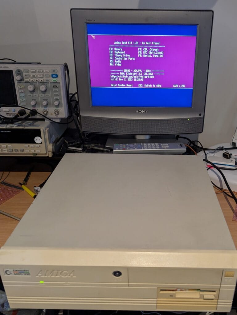
Just in time because a couple of hours later, it was collected by its new owner to take to an event.
Next time
There will be a little break before the next part in this story, I am going to be working in India next week, I also have some other repairs to catch up on. But, the following things are still to be done as part of this series:
- Jools will be coming back for new SIMM sockets and to replace that 7407. I may be installing some upgrades too.
- Jops needs deeper investigation and repair.
- Those four hard drives need archiving. I will share the process for this, but not much of the data at first. This is mostly for Stoo to consume and distribute as he sees fit.


Leave a Reply