
The RGBtoHDMI project uses a Raspberry Pi Zero to generate an HDMI output based on the video signals from a classic computer. A CPLD is used to convert these signals into a common format for the Pi to read on the GPIO. This post goes into why and how I developed an Amiga 500 variant of this.
History
Whilst I don’t know the full history of the project, I believe it started as a way of getting an HDMI output for Acorn computers and extended to other platforms. c0pperdragon created an Amiga 500 variant which worked a little differently. Instead of using a CPLD it uses fixed logic gates to sync everything correctly.
It has a jumper to switch between Denise and Super Denise video chips in Amigas because the timings are slightly different between them.
But, there are down sides to this design. First of all physically the adaptor locates the Pi in such a place that it makes it very difficult to use an accelerator such a TF536. More importantly every Amiga appears to have slightly different timings. This has caused users to have a sparkling effect in some areas of the screen as the pixel clock is ever so slightly out of sync. This issue was further complicated when there were attempts to relocate the Pi and therefore making some of the connections from the logic to the Pi slightly longer, almost guaranteeing there will be issues.
There are workarounds for this, but IanSB, who is a heavy contributor to the RGBtoHDMI project, suggested a solution based around an adaptor which connects to the common CPLD board would be a better design that eliminates these kinds of issues.
My Design
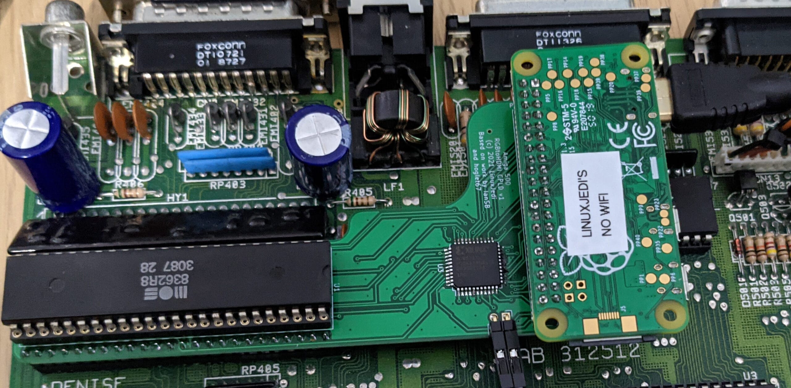
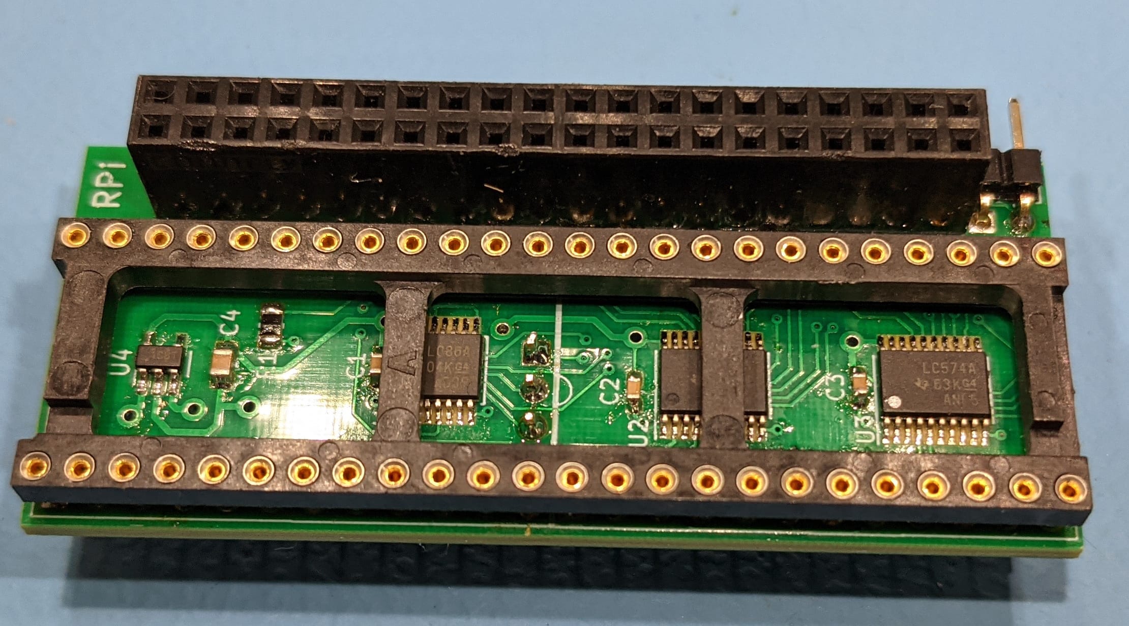
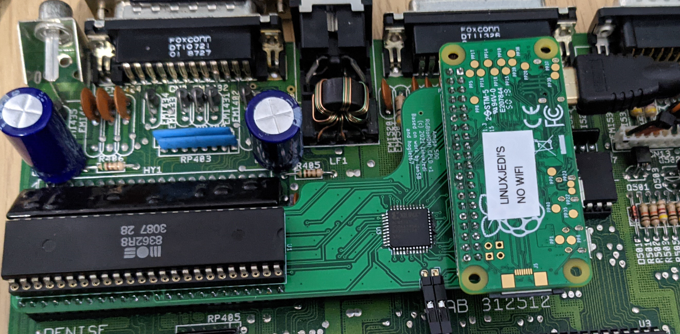
I agreed with IanSB’s assessment, but I figured with the Amiga a simpler physical implementation was possible. Instead of an adaptor board for Denise and a separate CPLD board for the Pi, I decided to combine everything into a single solution. I also made the design relocate the Pi to the side so that there was a much better clearance for accelerators.
There were a few initial teething problems getting this working properly, in theory the software on the Pi should enter recovery mode on first boot to flash the CPLD firmware. Unfortunately this particular menu was designed for three buttons. I decided to go for a single button design to better align with how users expect it to work based on previous designs. Even hard coding single button mode on does not work correctly for this menu. For my first prototype I physically soldered on temporary wires to act as the buttons.
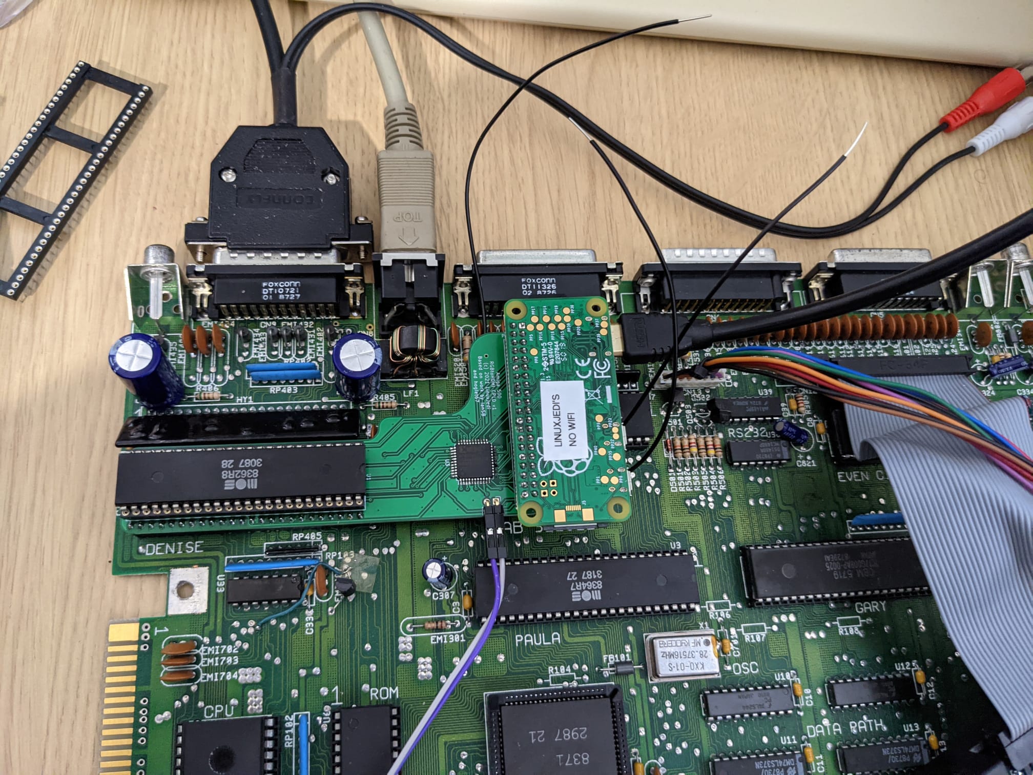
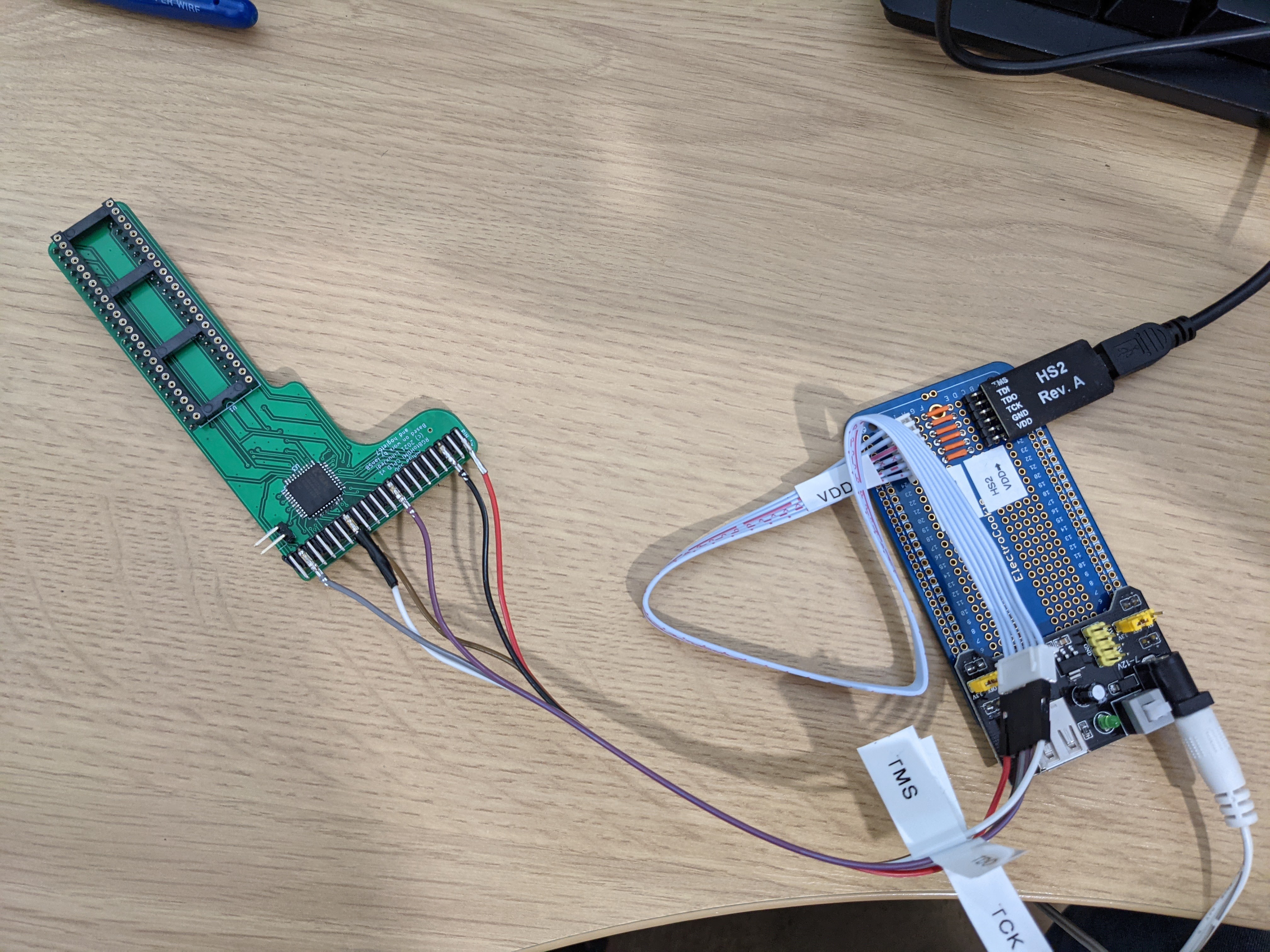
For subsequent boards I hacked together a connector for my JTAG programmer so I could flash the initial CPLD image from the Pi.
After this and some software configuration tweaks we are good to go. This design has been tested on several different Amigas now and on some of them an initial calibration is needed, but this is very simple to do any only needs to be done once. If you raise a TF accelerator by one CPU socket it also fits pretty well.

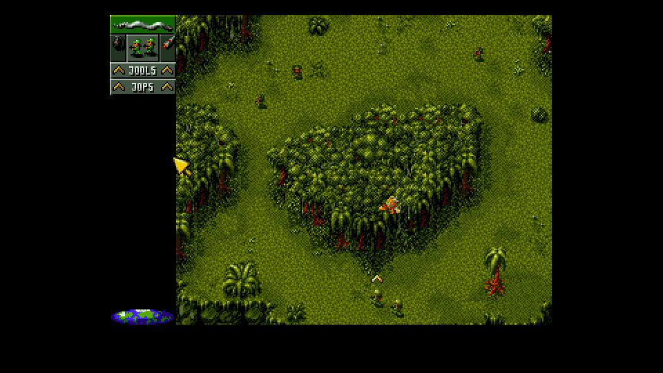
The image is pixel perfect and it can be softened or scanlines added. Due to the completely different way the pixel clock is derived (using the RGB and sync instead of the Amiga’s clocks) there is no sparkling pixels.
Once this was fully tested and I was able to write up all my notes, I released this project as Open Source on GitHub. Now anyone can go build one!
Leave a Reply