
Nearly a year ago I wrote about a way to program Xilinx XC9500XL series chips from a Raspberry Pi. Since then a new version of Raspberry Pi OS has been released which completely breaks this and there are new tricks I’ve created which may be useful to some. So, this blog post is a revisit of the subject with a new tutorial.
Update 2025-02-12: Raspberry Pi OS version Bookworm and the Pi 5 broke all of this again, new instructions available here.
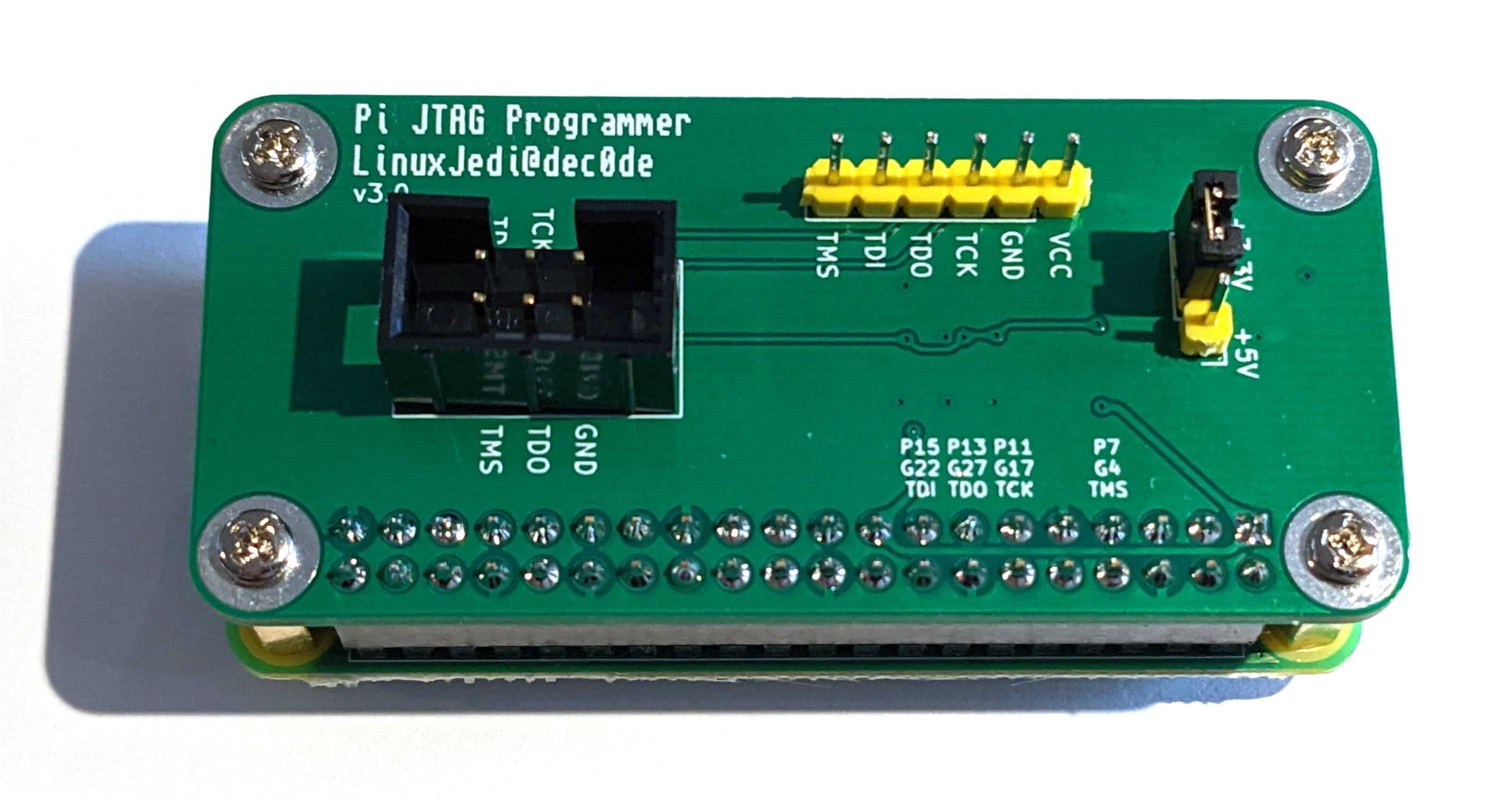
Update 2022-10-02: I have designed a Pi JTAG board to make the wiring even easier with protection voltage translators for the Pi. It is available here.
Update 2022-05-20: Thanks to Eriond for pointing out that a username and password is no longer automatic. I have added a section for this.
I’ve adjusted this tutorial so that it will work with any Pi version currently available, but I have used a Raspberry Pi 3A+ for the examples. I’m going to be doing this completely headless, but feel free to use a monitor and keyboard to make things easier. This tutorial is written with Linux in mind, it should work in macOS too and likely Windows PowerShell.
Pi Software
First thing you are going to need (beyond a Raspberry Pi) is the Pi OS. You can use the installer from the Raspberry Pi Website. I recommend selecting the “Lite” version for this but any version will work.
Once you have installed this on an SD card, mount the “boot” partition on your computer and create an empty file on it called “ssh”, in Linux and macOS you can do this by typing touch ssh in the command line. This will turn on SSH access.
Now create a file called wpa_supplicant.conf with the following contents (alter for your WiFi settings, the ssid and psk details are case sensitive):
ctrl_interface=DIR=/var/run/wpa_supplicant GROUP=netdev
network={
    ssid="YOUR_SSID"
    psk="YOUR_WIFI_PASSWORD"
    key_mgmt=WPA-PSK
}
Finally you need to have a user created as this no longer happens on boot, if you create a file called userconf.txt with the following contents you will have a username ‘pi’ and password ‘raspberry’:
pi:$6$4VKVEKkbxmVaadgx$1yOzCvT58onJsH5UdWhnpksIaHtFTVCnJ8lydLCEAfzJ43S3RXrYQYZXfZcXWZJHP9Ea0J9lWbHmwGScac3Ni/
You can safely eject the SD card, put it into the Pi and turn it on. The first boot will take a few minutes as it resizes the filesystem to use the whole SD card and a few other first-boot things.
The following command will let you SSH into your Raspberry Pi:
ssh pi@raspberrypi.local
Now that you are on the Pi, this set of instructions will install the latest xc3sprog tool to flash Xilinx chips. I’ve spent a long time trying to get OpenOCD to work with Raspberry Pi and Xilinx CPLDs but it never quite works right, whereas xc3sprog makes it easy:
sudo apt update
sudo apt -y dist-upgrade
sudo apt install build-essential libusb-dev libftdi-dev libgpiod-dev git cmake
git clone https://github.com/matrix-io/xc3sprog
mkdir xc3sprog/build
cd xc3sprog/build
cmake .. -DUSE_WIRINGPI=OFF
make
sudo make install
Note that we are turning “wiringpi” off, this is no longer supported in the latest Raspberry Pi OS, which means we have to use another access method called “sysfsgpio”. This works with any Pi version but is about 50% slower and requires “sudo” to work. It is still fast enough for daily usage and removes the need for you to have to compile “wiringpi” yourself.
JTAG Wiring
This is the default wiring pinout for xc3sprog:
| Pin | JTAG |
| 7 | TMS |
| 9 (or any Ground pin) | GND |
| 11 | TCK |
| 13 | TDO |
| 15 | TDI |
| 17 (or pin 1) | 3V3 |
Note that if you wish to wire this differently, for example if the Pi is already wired to your CPLD in board such as the RGBtoHDMI, you can edit sysfscreator.cpp and recompile. Here you will see the code:
IOSysFsGPIO(4, 17, 22, 27)
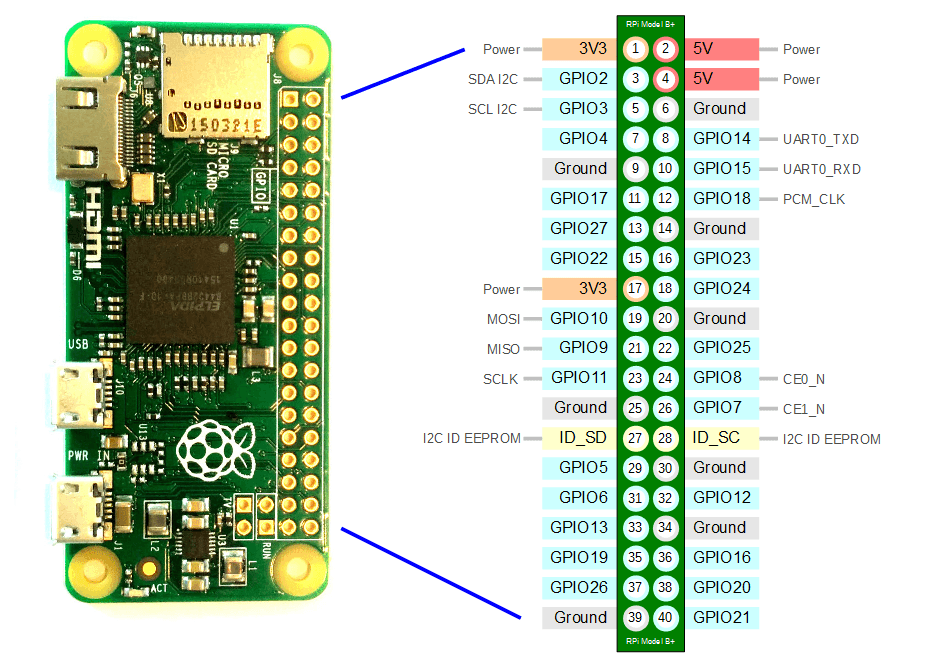
These are the GPIO numbers, not pin numbers so are in the order of TMS, TCK, TDI, TDO. The mapping can be seen in the image below:
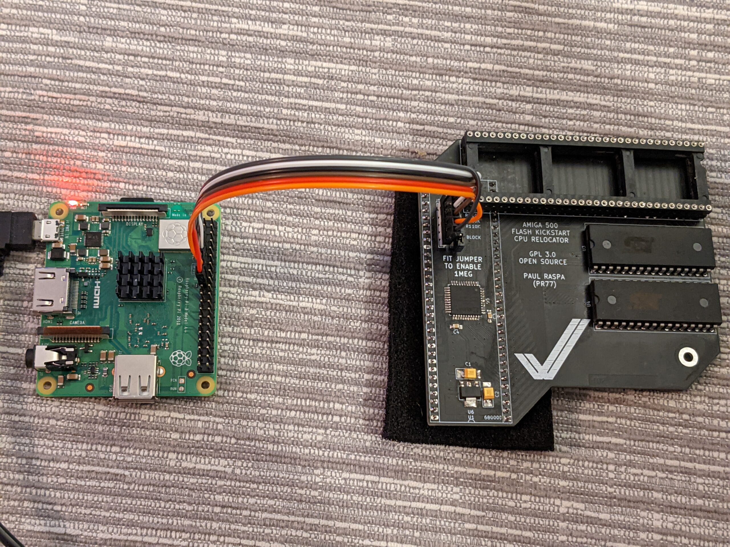
This is what it looks like wired to an Amiga Flash Kickstart board:

Using xc3sprog
The first useful command is:
sudo xc3sprog -c sysfsgpio_creator -j

This probes the JTAG chain and lists everything on it. For example, some Terrible Fire cards will identify two Xilinx chips on it. This is useful because in subsequent commands you can specify which chip you are talking to with the -p parameter. Since there is only one chip in my chain, we will just be talking to that one:
sudo xc3sprog -c sysfsgpio_creator -v -p 0 myxilinx.jed:r
sudo xc3sprog -c sysfsgpio_creator -v -p 0 FLASH_KICKSTART.jed
The first command here reads the Xilinx chip and saves it to disk, the second one writes new firmware to the Xilinx chip.
Remote Programming
It is possible to use the Pi to remotely program from your computer. First of all it may be useful to copy your SSH public key over to the Pi. There are dozens of tutorials on this so I’ll skip this for now, it just saves you having to enter a password every time. Then the command from your laptop is:
ssh pi@raspberrypi.local 'cat > /tmp/FK.jed && sudo xc3sprog -c sysfsgpio_creator -v -p0 /tmp/FK.jed && rm -f /tmp/FK.jed' < FLASH_KICKSTART.jed
This basically reads the local FLASH_KICKSTART.jed file, copies it to /tmp on the Pi, runs xc3sprog on the Pi and then deletes the file. Unfortunately xc3sprog can’t read from STDIN, tricking it to do so will cause the verification step to fail.
Makefile
Finally I’ve created a small Makefile which can compile the the Xilinx Verilog and also use the remote programming step above as the “make install” step. You’ll need Xilinx ISE WebPACK installed and the /opt/Xilinx/14.7/ISE_DS/ISE/bin/lin64 in your path (assuming that is where you install it).
The Makefile is as follows, adjust for your chip and verilog file accordingly:
PROJECT=FLASH_KICKSTART
DEVICE=xc9572xl
PART=XC9572XL-10-VQ44

all: $(PROJECT).jed

%.xst:
	@printf "run\n-ifn $(PROJECT).v\n-ifmt verilog\n-ofn $(PROJECT).ngc\n-p $(DEVICE)" > $@
	@xst -ifn $@

$(PROJECT).jed: $(PROJECT).xst
	@ngdbuild -uc $(PROJECT).ucf $(PROJECT).ngc -p $(DEVICE)
	@cpldfit  -p $(PART) -ofmt vhdl -optimize speed $(PROJECT)
	@hprep6 -s IEEE1149 -n $(PROJECT) -i $(PROJECT)
	@hprep6 -s IEEE1532 -n $(PROJECT) -i $(PROJECT)

clean:
	@rm -rf xst
	@rm -f $(PROJECT).bld
	@rm -f $(PROJECT)_build.xml
	@rm -f $(PROJECT).gyd
	@rm -f $(PROJECT).isc
	@rm -f $(PROJECT).jed
	@rm -f $(PROJECT).mfd
	@rm -f $(PROJECT).ngc
	@rm -f $(PROJECT).ngc_xst.xrpt
	@rm -f $(PROJECT).ngd
	@rm -f $(PROJECT)_ngdbuild.xrpt
	@rm -f $(PROJECT).pad
	@rm -f $(PROJECT)_pad.csv
	@rm -f $(PROJECT).pnx
	@rm -f $(PROJECT).rpt
	@rm -f $(PROJECT).srp
	@rm -f $(PROJECT).xml
	@rm -f $(PROJECT).xst

install:
	@ssh pi@raspberrypi.local 'cat > /tmp/firmware.jed && sudo xc3sprog -c sysfsgpio_creator -v -p0 /tmp/firmware.jed && rm -f /tmp/firmware.jed' < $(PROJECT).jed
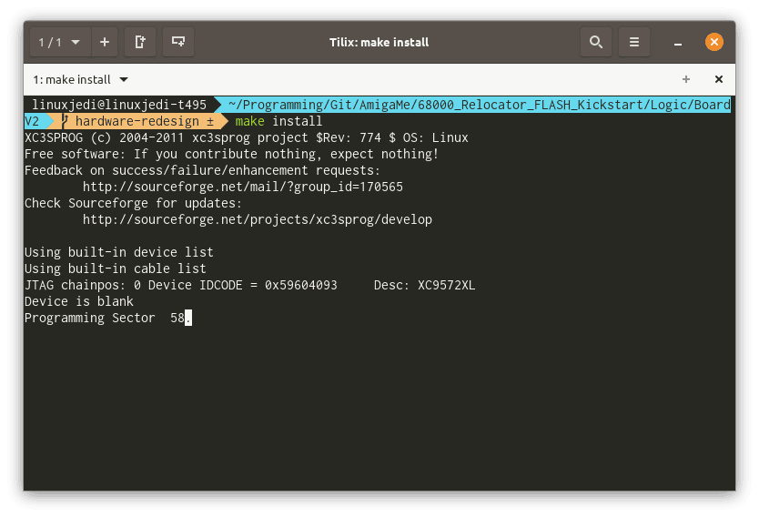
You can now run make to build the Verilog and make install to install via SSH:
Leave a Reply