
I was recently at FOSDEM in Brussels and noticed quite a few people walking around wearing digital badges. So, I thought when I get home I should see if I could cobble together my own one.
Introduction
Going through my box of microcontroller boards I figured this would be an ideal project to finally try out the Raspberry Pi Pico, I’ve got several of them but not had a project to apply them to yet. I also decided that I wanted a colour OLED display, this had to be large enough to show an image, but small enough that it wouldn’t be too much stress for a microcontroller. I decided on a SSD1351 based display. It is 1.5 inches in size with a 128×128 resolution supporting 65535 colours (in RGB565 format).
Wiring
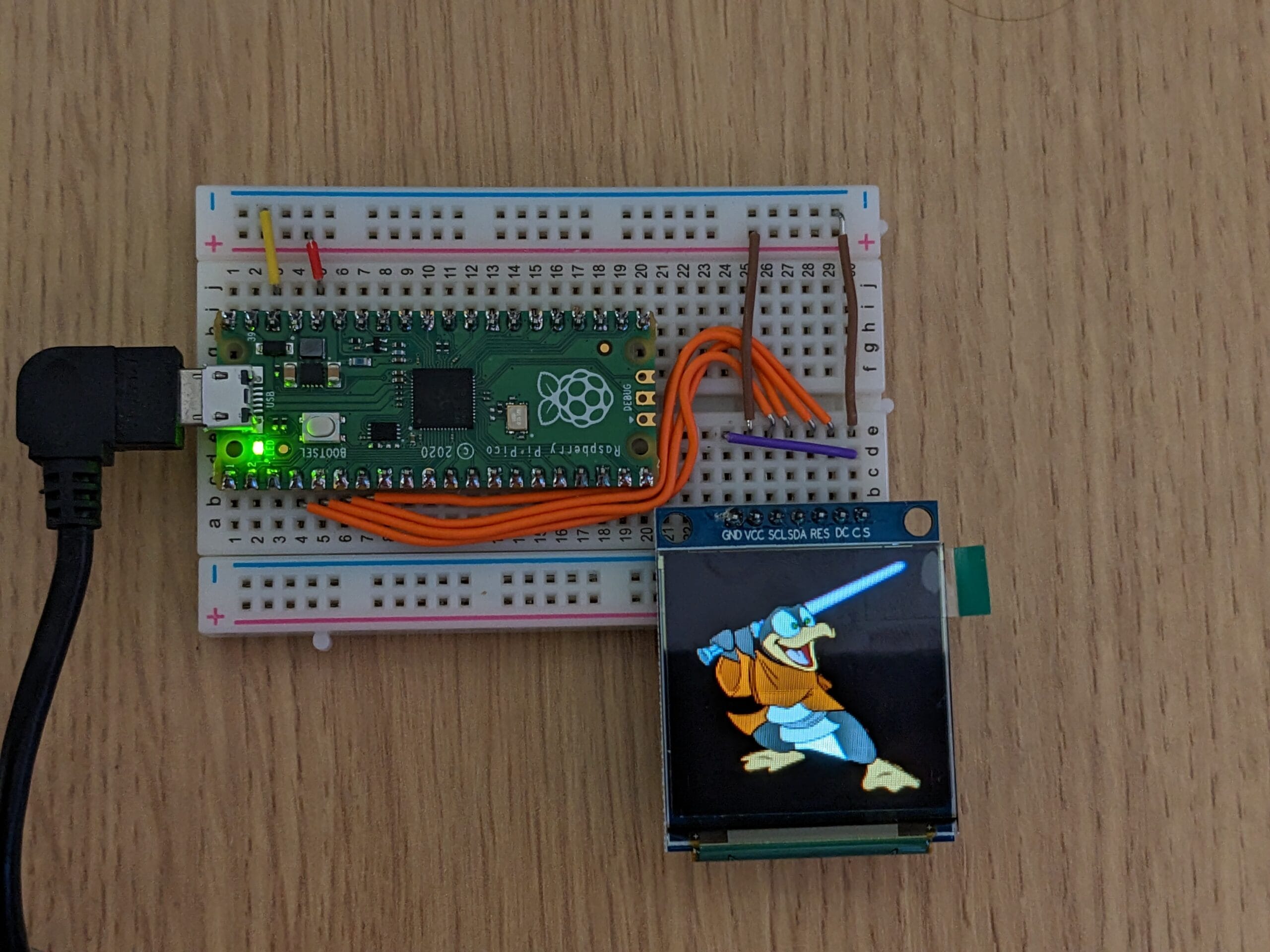
For now I’ve put everything together on a breadboard, it was pretty simple, picking some of the SPI and GPIO pins to control the OLED display, and the Pico’s regulator appears to be plenty to power the display.
What is SPI? For those who don’t know what it is, there are two common standards for connecting things serially to microcontrollers. These are I2C and SPI. I2C is more like a serial bus, is typically simpler to wire up but has quite a limited bandwidth. SPI is much faster and care is typically needed when wiring as it can be more susceptible to noise. But is ideal when you need high bandwidth. SPI connections at a minimum have a clock and data line for each direction. There is only one direction here so it is just “SCL” for “Serial Clock” and “SDA” for “Serial Data”. There is also CS which is “Chip Select”, since we only have one thing on the SPI bus we can hold this low (which means select this device), everything will be for the OLED display.

Wiring details are in the GitLab project later in this blog post.
Pico C SDK
I was dreading the software stack a little bit, I knew I wanted to write my own driver from-scratch so I can get a feel for how everything works. Many microcontrollers require you to install a huge IDE stack just to compile them. But not the Pico! In Linux you just grab an SDK from GitHub, link it in with a bit of CMake magic, and it just works!
Not only that, but when you boot the Pico into flash mode it appears as a drive on your computer, so you can just dump the file. Alternatively you can use a tool called picotool to flash it from the command line. I preferred this method personally.
When looking through the SDK I found that it has a fantastic DMA feature, basically you link a segment of memory to the SPI (or something else) and it will asynchronously pipe the data from the RAM to the SPI in the background, very quickly. Leaving the MCU cores to get on with other things!
The code was pretty easy to write, I’ve communicated with SSD13xx OLED displays before and this wasn’t massively different. There are PDF datasheets all over the web showing how to communicate to it.
Testing
I actually wrote the test code before I had put the hardware together. I wired it all together, loaded the firmware, and… nothing. No display. I looked through my code and found I made a small typo, I was clocking the SPI at 40MHz instead of 4MHz, which even if the OLED supported, would not be very stable with this breadboard wiring. Once this was fixed I tried again, and…

Well… it turned on, but wasn’t quite what I was expecting to see. Whilst eating dinner and going through things in my head I realised that I was sending the image data to the screen, but not the command to tell it I was sending image data. So what we are seeing here is the initial state of the RAM on the OLED display.
Next day I added the missing command and got an image:

Not perfect, but at least you can see what I was trying to display. Turns out I needed to byte-swap the image. Let’s try that again…

Looking much better, the diagonal darker strip seen here is due to the refresh rate of the screen combined with the camera rolling shutter. The naked eye could not see this.
Fonts and Animation
After this I added 8×8 font support and software scrolling to see what this was capable of.
Going pretty well, after this I managed to improve the speed a little more by having two buffers. One frame buffer is being sent via the DMA to the OLED whilst simultaneously the next frame buffer is being prepared. It means that it is doing the scrolling at roughly 60fps. This is pretty much hitting the max limits possible with the 20MHz SPI.
How It Works
I have put the source code on GitLab, it is currently a work-in-progress whilst I add more features. There is also a quick script to convert a 128×128 PNG to an RGB565 image in a .h file to be rendered by the application.
The RGB565 format basically means 16bits per pixel, giving 65535 colours. 5 bits for red, 6 bits for green and 5 bits for blue. There are two buffers created in memory that are 128x128x2 bytes each (32KB each) which is a single frame of the image. The application writes to one of the buffers, filling it with an image, moving bytes around the buffer to make scrolling happen, etc. Whilst the other buffer is being flushed to the SPI by the RP2040’s DMA controller. If the DMA controller is still writing out when the next frame is ready, it waits until the first frame is complete. The DMA has a command to block until complete. A 1ms pause is needed once the DMA has unblocked, because the transition between data and command toggling can be too fast for the display to handle. The Pico by default is running at 125MHz so there are plenty of cycles to play with the 32KB buffer in the time it takes to send 32KB at 20MHz.
What’s Next?
More functionality to begin with, larger font handling, maybe colour handling with fonts. Then a single PCB for the whole thing. I’ll continue to update the GitLab repo as I go, so watch this space!
Leave a Reply