
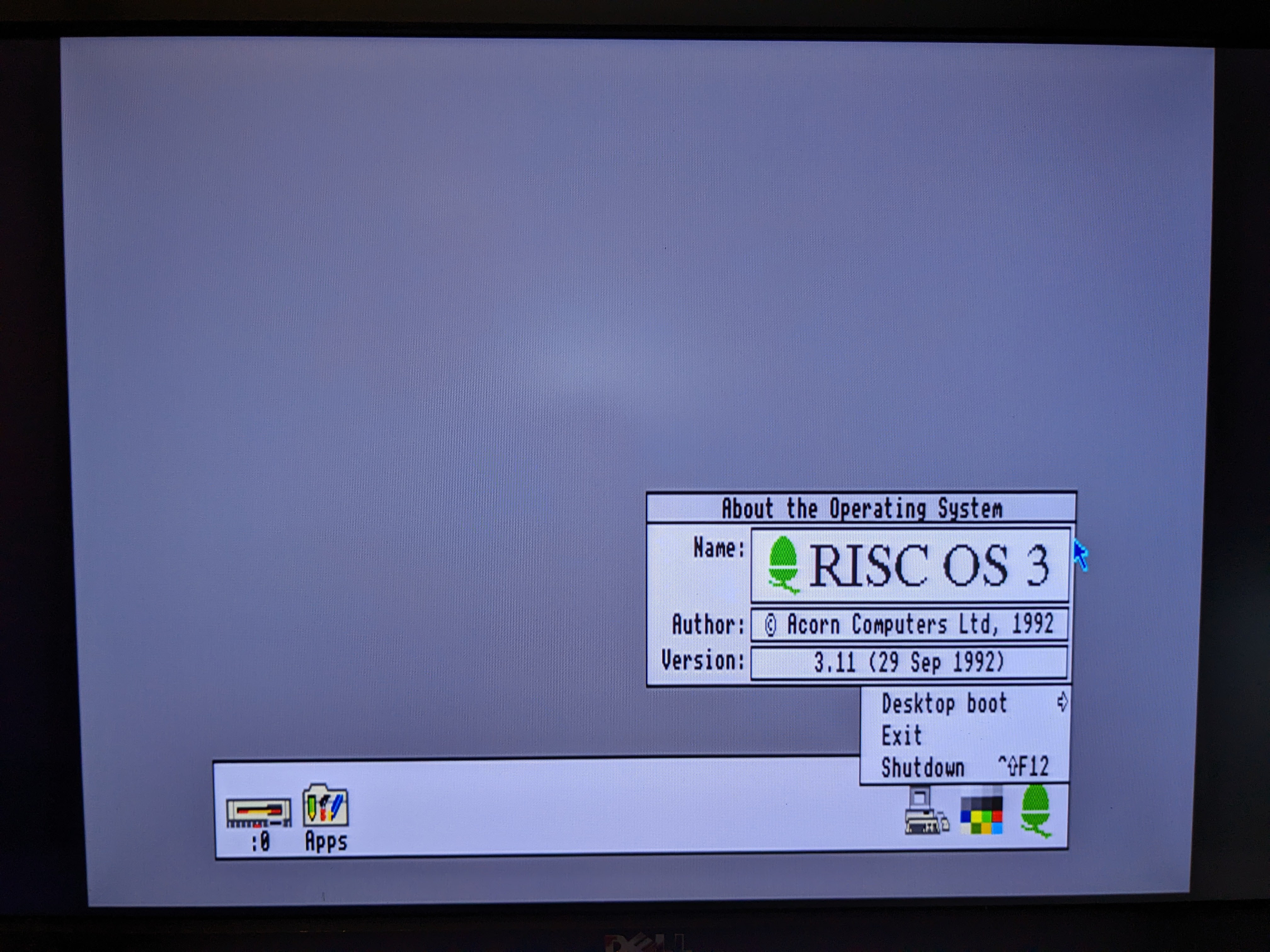
I last left this machine in a state where it boots RISC OS 3.11 when using a bench power supply, but there was a weird video issue which meant I could only use an OSSC for the SCART to work.
Video Learnings
I went to bed with a theory that the RGB select line wasn’t working properly, SCART takes a couple of possible signals. The first is composite, basically the same as the single yellow connector for a yellow, red, white composite cable. It also supports RGB with CSYNC, to switch to this mode a pin in the SCART is pulled high. My theory was that this wasn’t pulled high properly. For OSSC this doesn’t matter, likely because it has very smart signal detection. This was confirmed with a Tweet the next day:
Looking at the schematic we can see what LK25 does.

So, when set LK25 makes the pin the VSYNC, when unset it is pulled high with a 22K resistor. This can also be seen in the service manual:

In theory for SCART the jumper should be unset so that this is held high, with the default of LK24 set to CSync. Setting LK25 “worked” with the three TVs I tried, but in all of them the image was unstable. This is likely because the +5V was a signal instead of a stable line. My guess is the 22K resistor for the pull-up is too weak. I’ve seen photos of hacks which use a resistor of a few ohms to pull the pin high a lot stronger. I suspect this problem is why I heard rumour of a battery powered SCART cable for A3000s, the battery providing the the pull-up required to put the monitor into the correct mode.
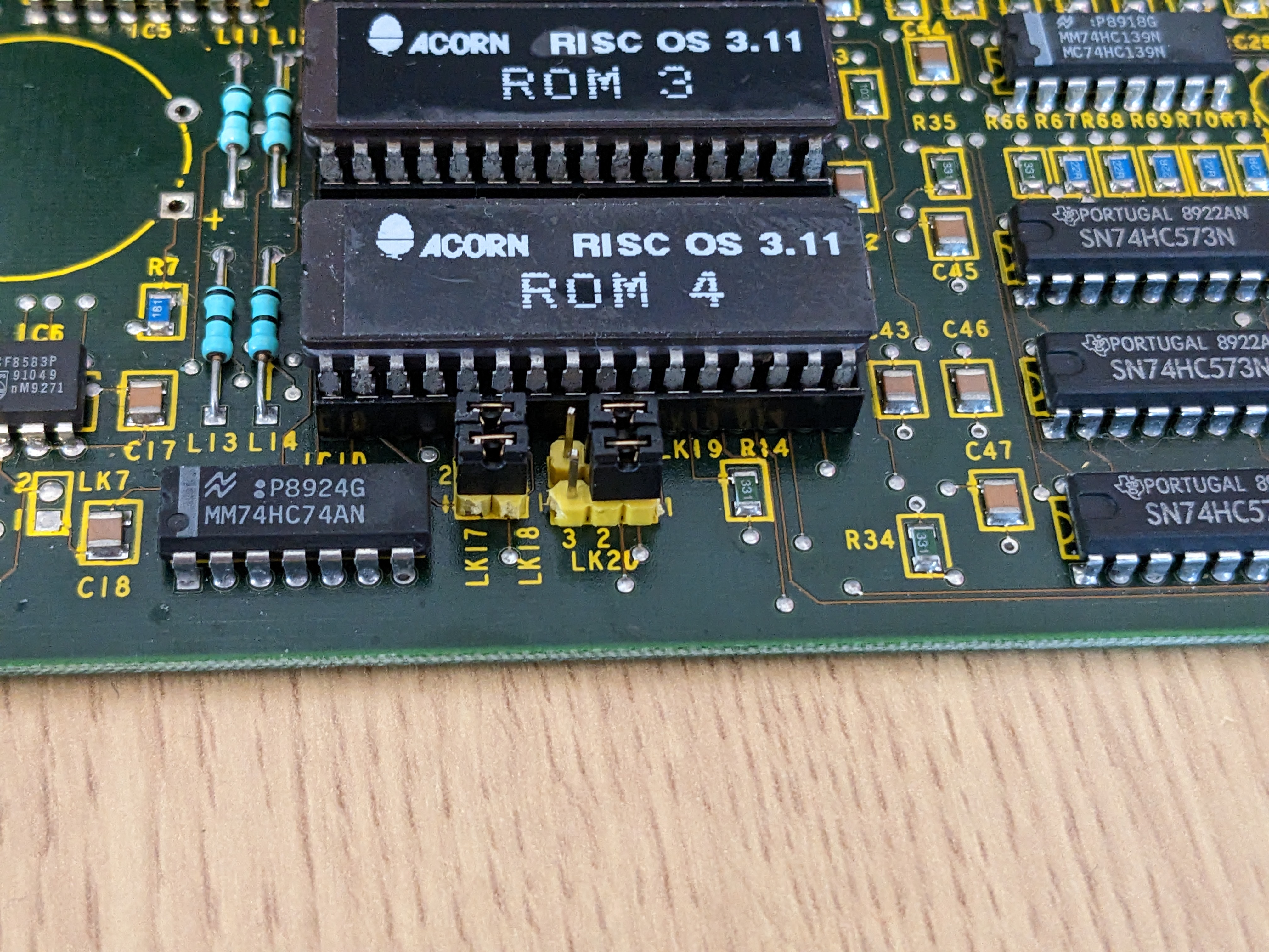
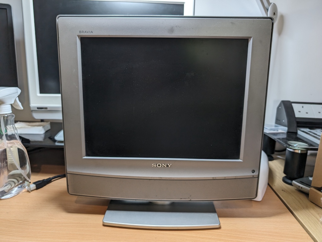
In the end I decided to do things another way. I bought this 9pin -> 15pin RGB to VGA cable from Amazon. Despite the description being a bit weird, talking about RS232, and even the pinout using RS232 terms, the wiring was correct for video. VGA typically uses RGB with HSync and VSync. So, I set LK25, moved LK24 to 1-2 plugged the cable into my 15Khz capable Dell P2214Hb (highly recommend grabbing one for retro machines if you find one) and turned it on.

I’m much happier with this setup, and I can use it for OSSC when I want to do video capture as well.
Battery
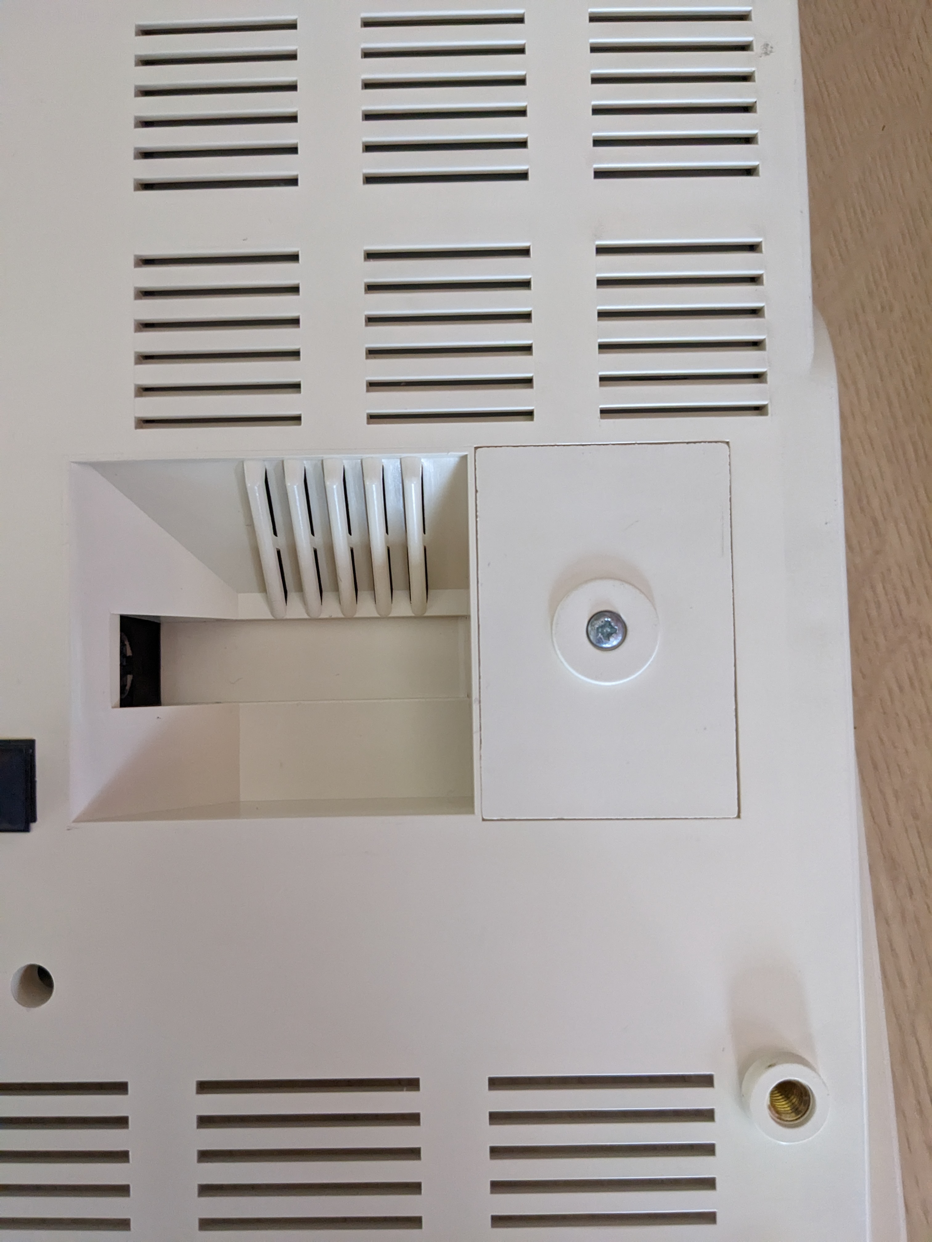
I made an interesting discovery when looking over this machine that I suspect other A3000 owners are aware of, the bottom half of the machine has a battery compartment that appears to have been designed for two AA batteries:
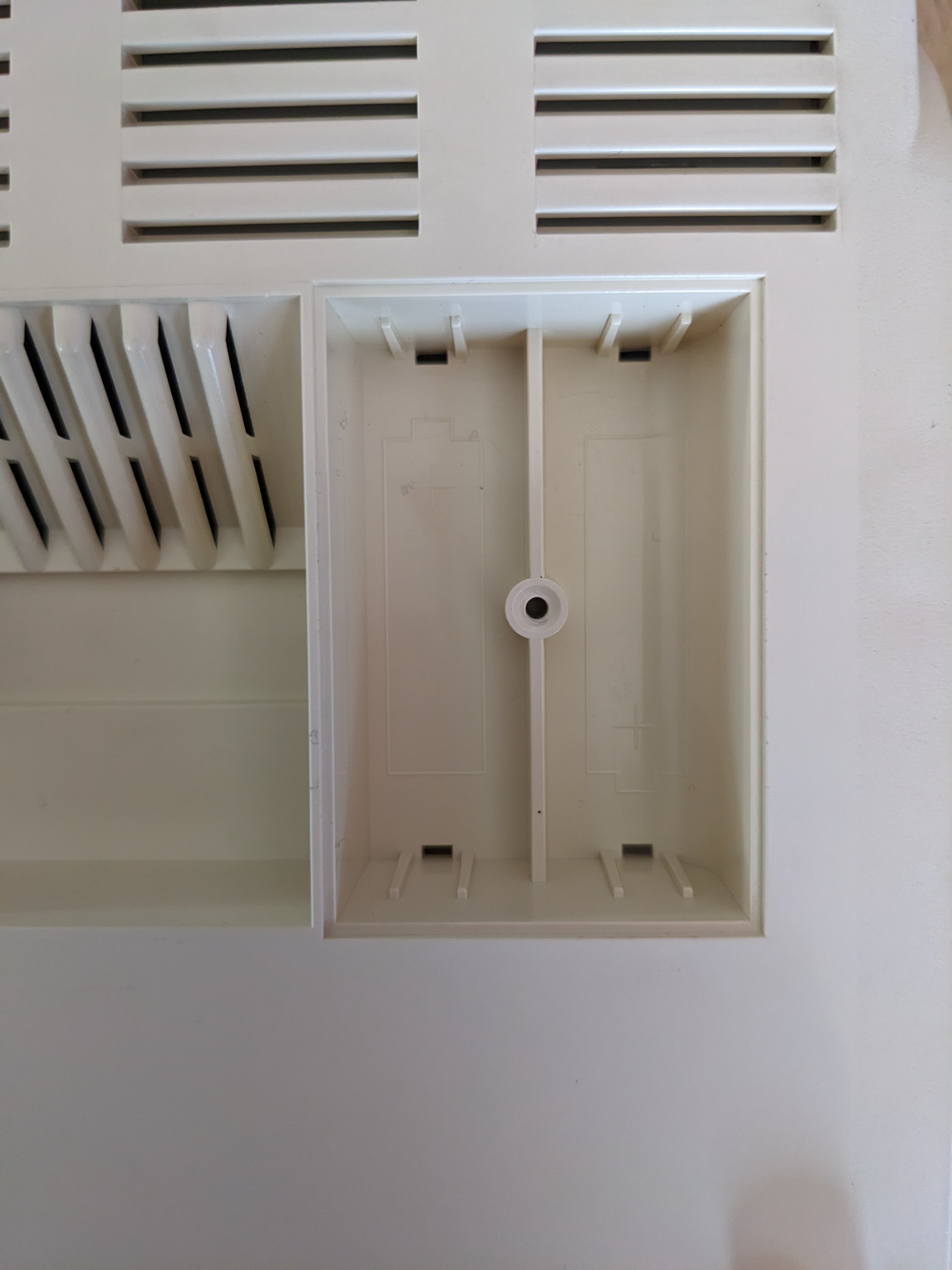
There are no contact springs in this, but I should be able to find some. What was more surprising is a part of the schematic.
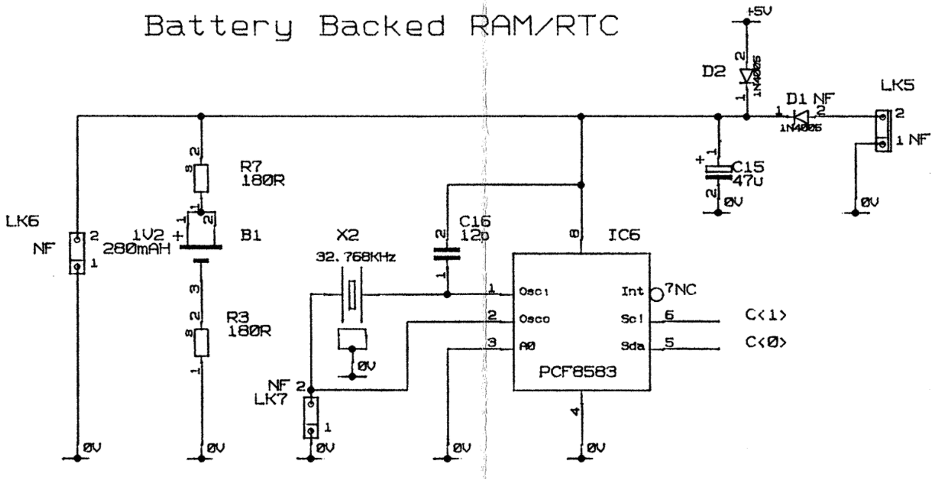
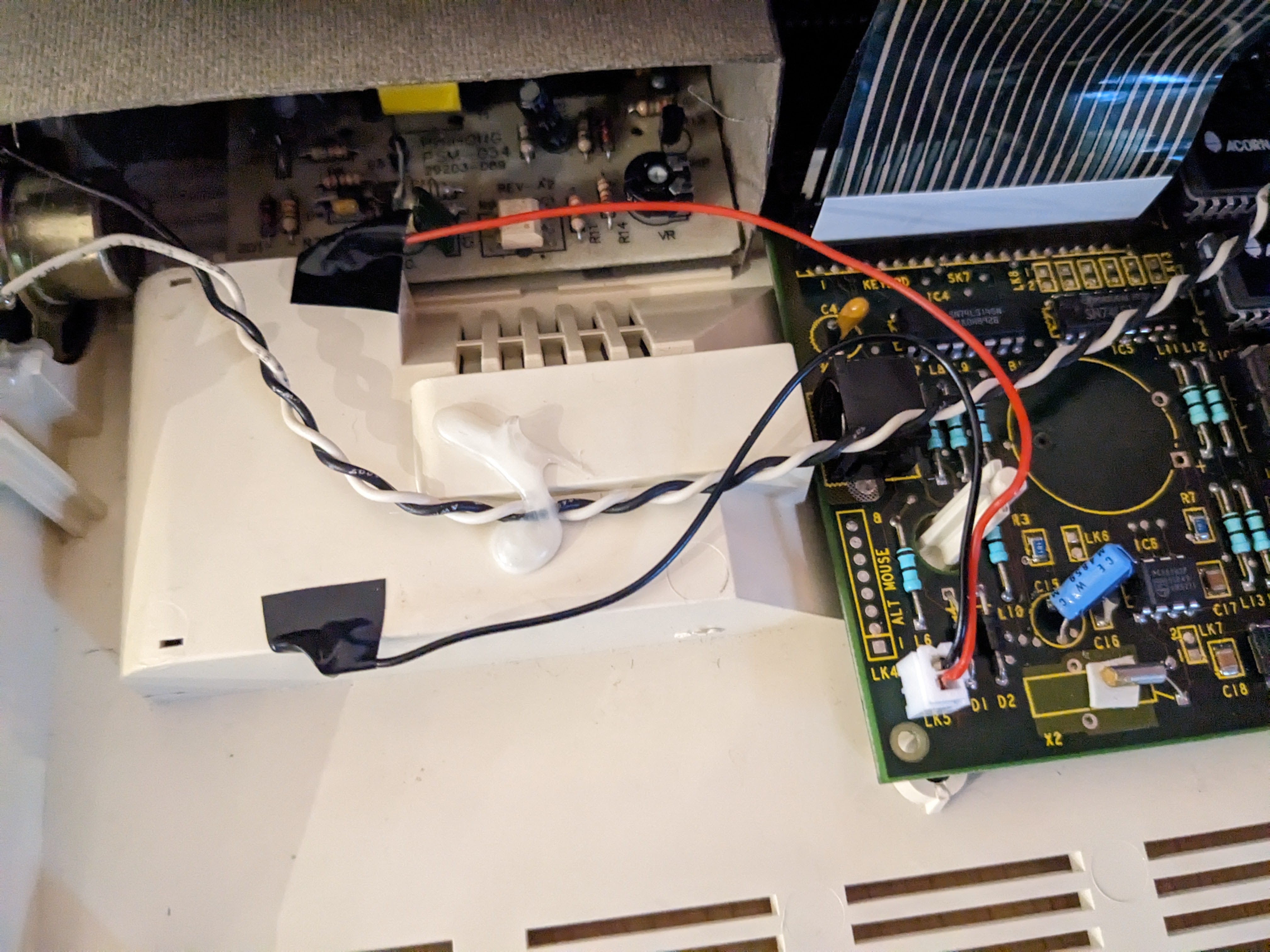
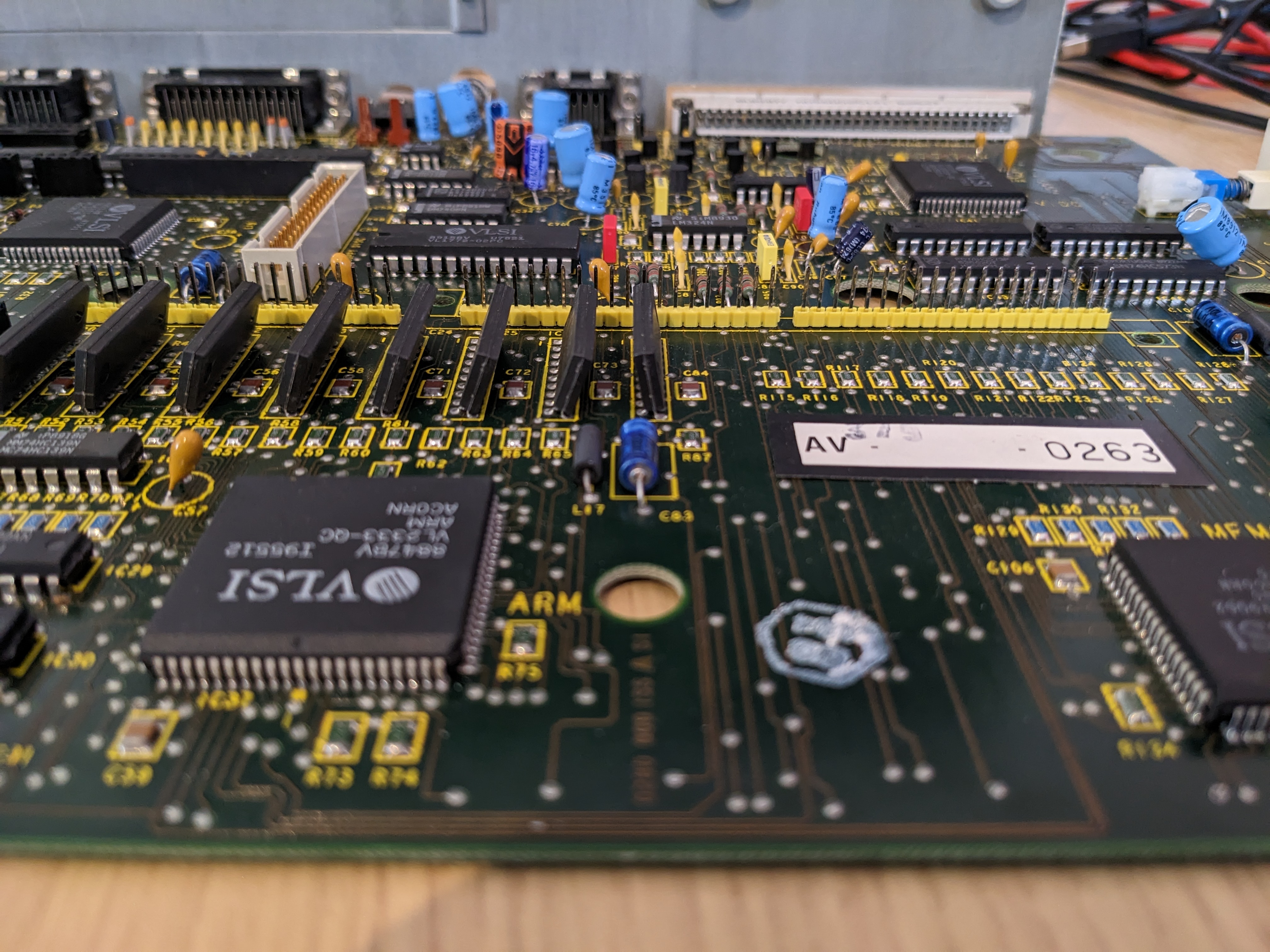
Now, I don’t know if this is true, but if I would hazard a guess I would say the non-populated D1 and LK5 were for the battery compartment. They can be found right in the bottom of the board.

On the board they are in the far bottom left, looks like LK5 was intended to be a molex connector, which would make sense so that polarity could be set. I later found this part of the service manual which appears to confirm my suspicions:
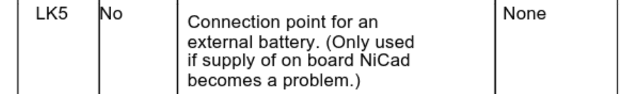
With that I soldered on the diode and a keyed connector for LK5.

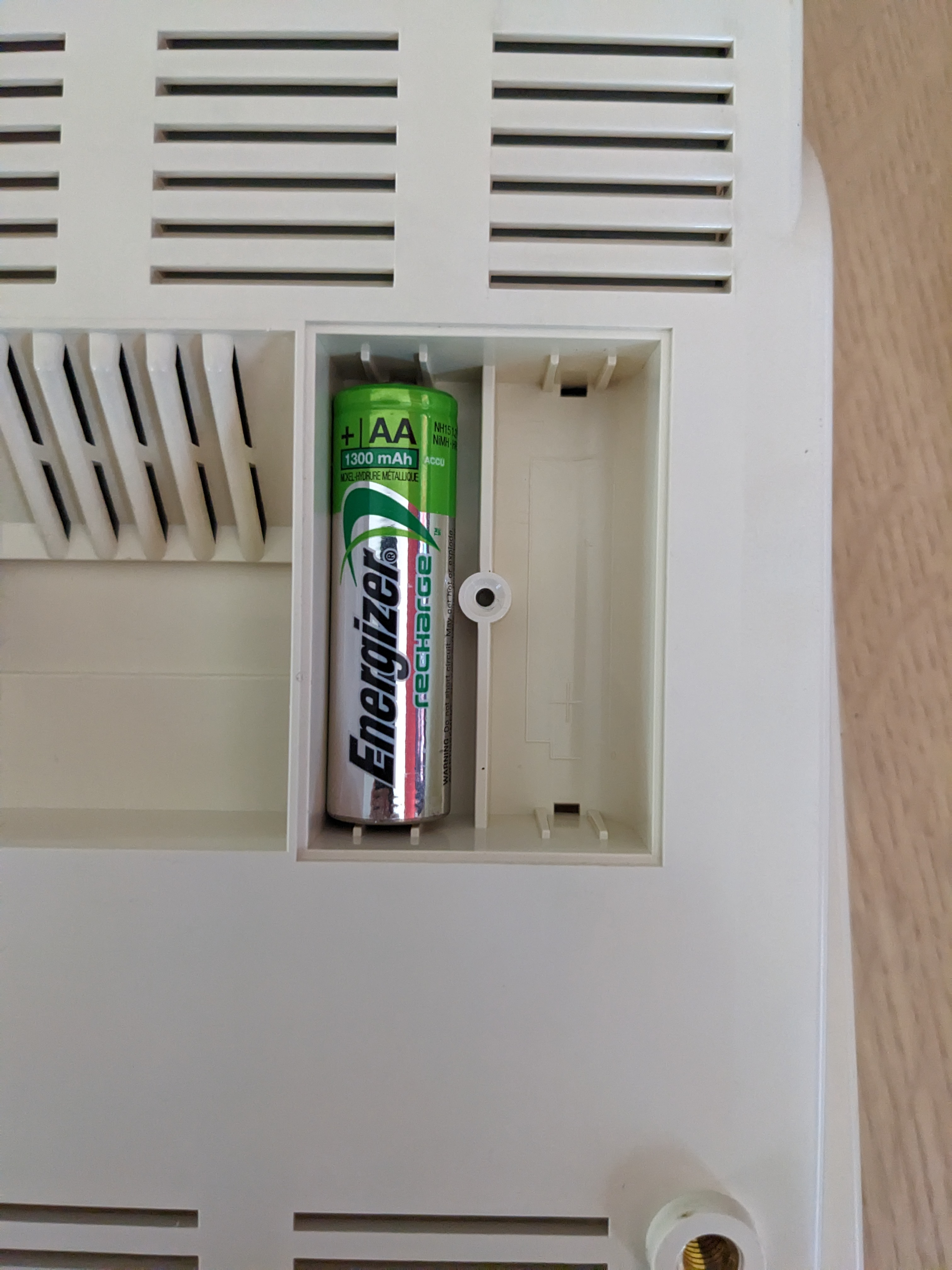
I found some battery contacts that fitted, and used a 3.6v non-rechargable lithium battery (ER14505) as the battery. The end result looked like this:
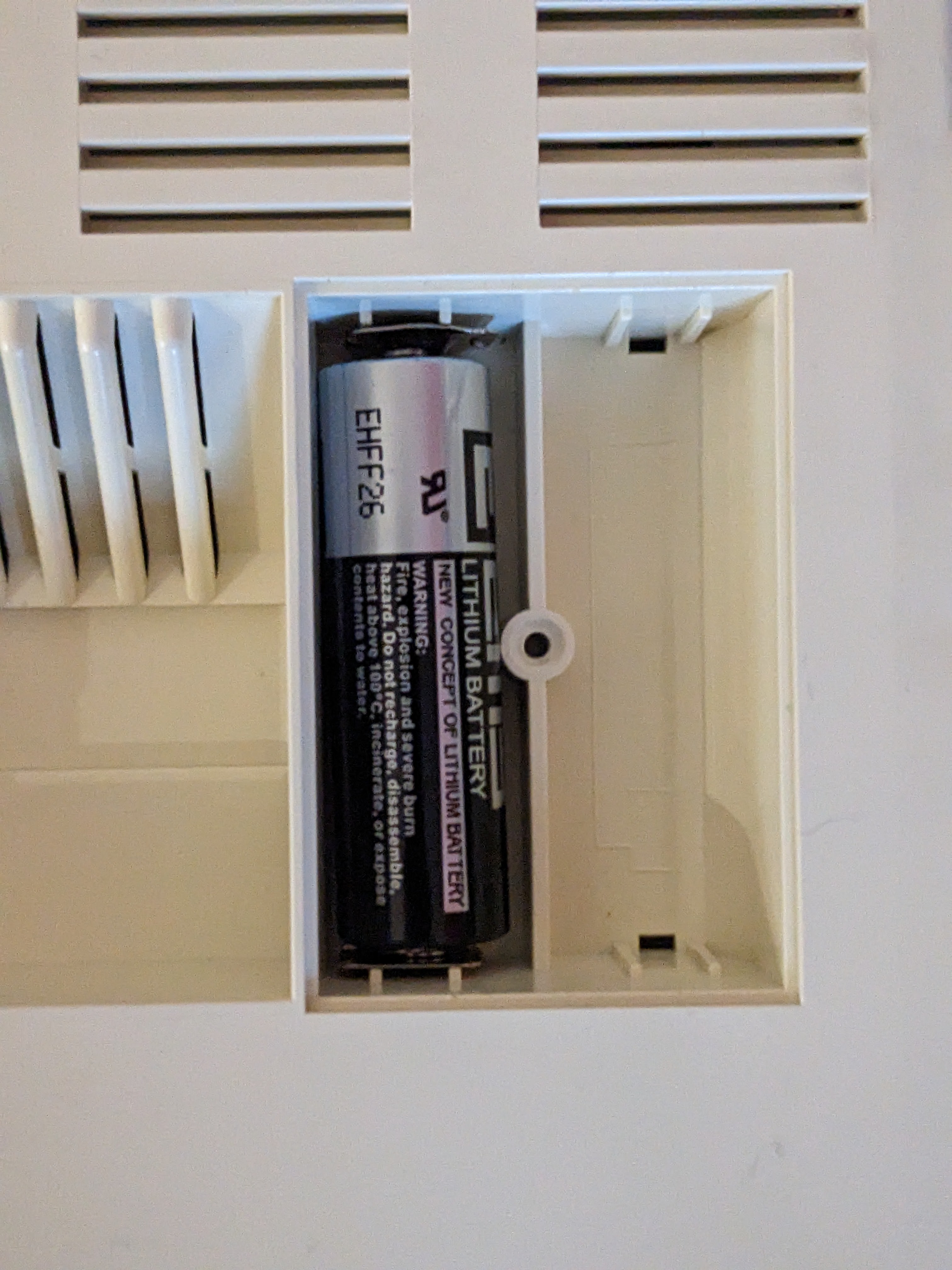
Everything tested out OK, so now I have a battery solution that doesn’t require disassembling the machine. This battery should be good for probably a decade anyway and shouldn’t leak.
Pin Headers
The motherboard’s pin headers all have corrosion around the plastic of the pin headers for some reason. So, using my Hakko FR-410 they all came out. This is a photo of some of them.
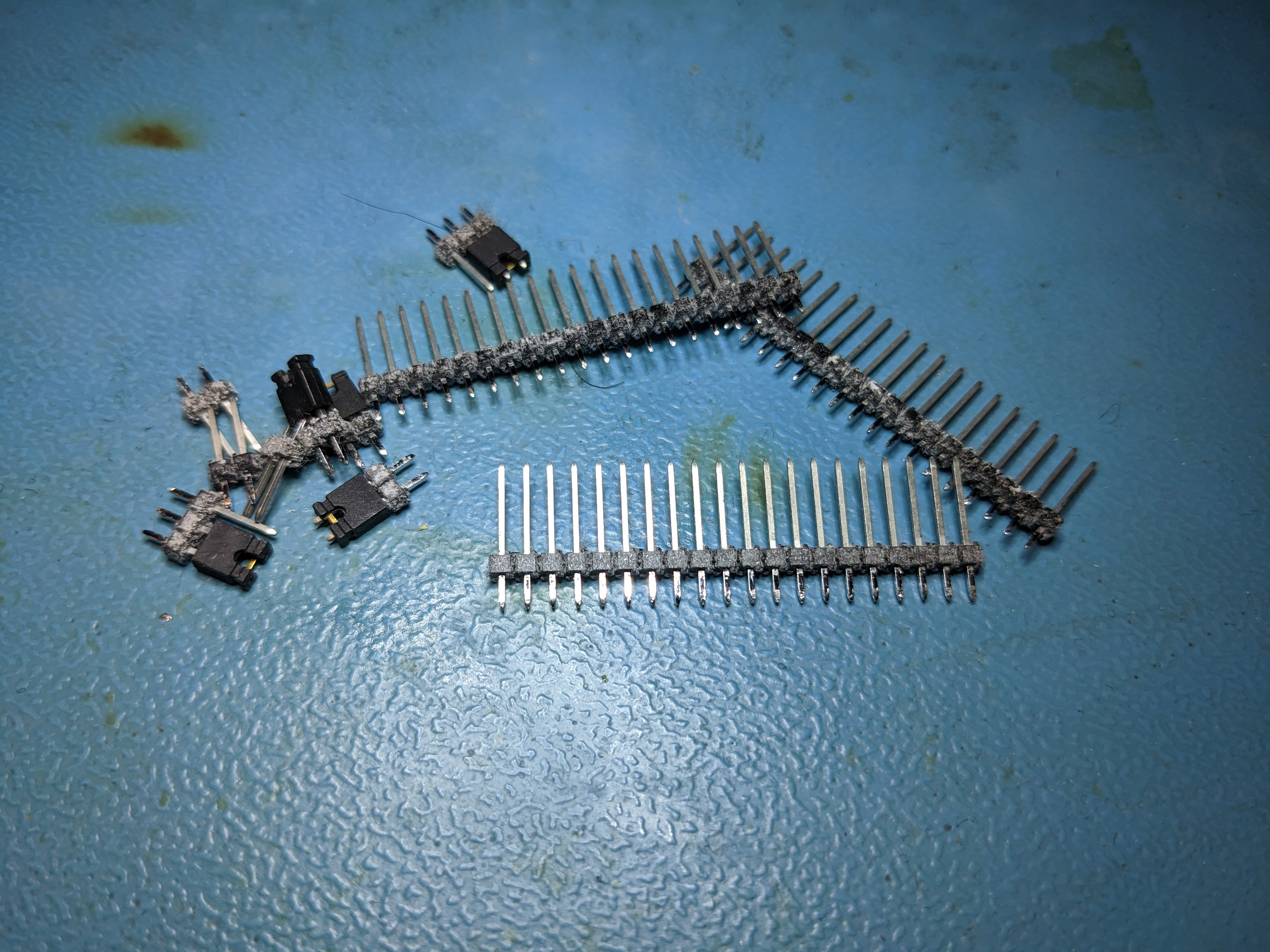
The longer strips there are from the RAM upgrade area. The only strips I have in stock to replace it are yellow, so I went with yellow for replacements everywhere. I think it goes quite nicely with the colour scheme used for the PCB itself.
Disk Drive
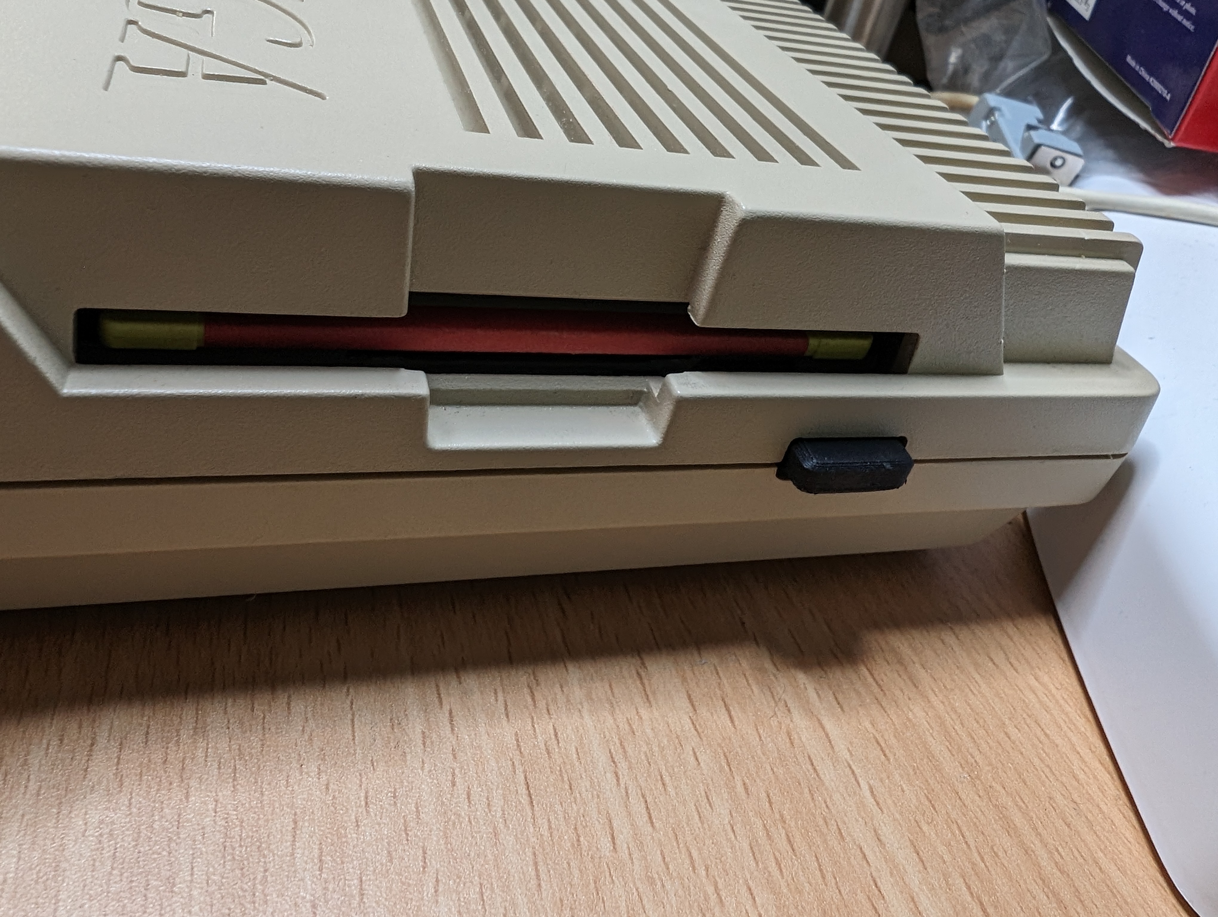
I wanted to cleanup the floppy drive, this was a simple case of cleaning the plastic face, re-greasing the worm gear and cleaning the heads. I then hooked it up to my greaseweazel to test reading a disk.

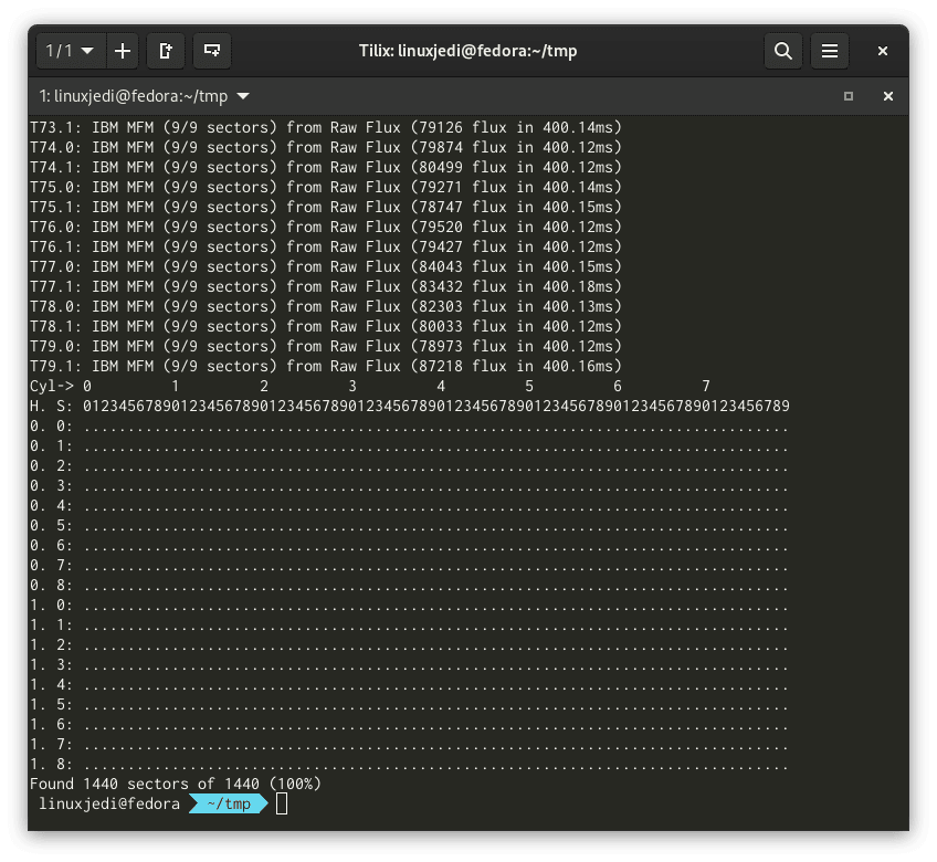
Excellent! Looks like the drive works!
Mouse
I did previously mention that I misplaced my Archimedes 3010 mouse which I intended to test this machine with. After that post I managed to find it amongst my Amiga gear from OLL23, not sure how it got mixed up there. But…
I managed to win an auction for two Archimedes trackballs. I believe with a high certainty that these were owned by an ex-Acorn engineer who unfortunately is recently deceased. Here they are next to my Kensington Slimblade which I used on the computer I’m typing this blog post on.

I took the one with the black ball/buttons and tried it out on the A3000, it worked great so I set to work cleaning it up. The top part was cleaned in a sink with washing up liquid. The insides were cleaned using cotton buds and the bottom, buttons and wire were cleaned using baby wipes. The ball was cleaned using a plastic cleaning spray and cloth.


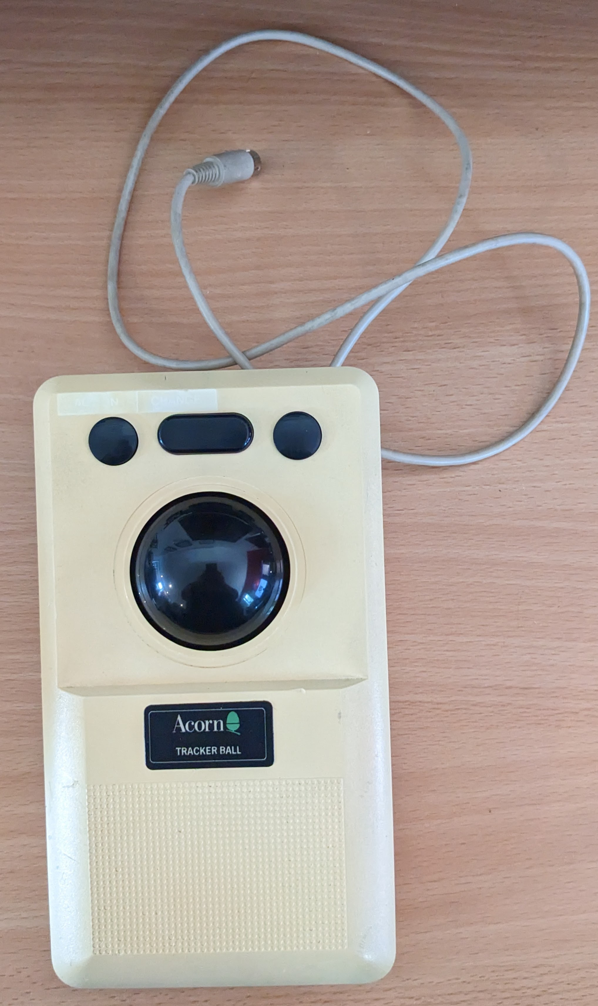
It’s not perfect, but a lot better than when I started.
Next Steps
All that is left is cleaning, PSU and putting it back together. Watch this space!


Leave a comment