
With one machine down and with what, I think, is the diagnosis of the final issue with the second one, it is time for the home stretch.
IDE Address Buffer
I previously diagnosed the 74HCT174 IC that runs the address buffering for the IDE port as bad, but I didn’t have a spare. It just so happens that later that day, an Amiga 1200 landed on my bench for restoration. That Amiga 1200 had a completely failed hard drive. On that hard drive was a 74HC174 IC in the correct SOIC form factor.
The main difference between the HCT and HC variant is the HCT is designed to operate at TTL voltage levels and the HC is designed to run at CMOS. TTL low is about 0-0.8v and high is about 2-5v. Whereas for CMOS this is roughly 0-1.5v low and 3-5v high.
In theory, this should be fine, it might only be an issue with a 68060 CPU that operates at 3.3v, but even then, things should be OK. Especially because the address lines are pulled up to 5v anyway.
So, with that out of the way, it is time to install the chip, U907 in this photo.

I plugged in a compact flash IDE card which has some Amiga partitions and loaded SysInfo to see what we can find.

The partitions are seen and can be talked to! We have a functioning IDE port!
Hot Stuff
I mentioned in my last post that a ceramic capacitor had decided to turn up the heat, going well over 100°C in a few seconds. This has been replaced and running the thermal camera again I managed to find another one getting hot. I missed this before as the camera pointed to the hottest spot last time.

Again, the calibration is off to the side, but it is clear that the capacitor is generating the heat. Not quite as hot as before, but it needs replacing.
Once this one was replaced, I could not find any such hot spots with the thermal camera.
Reassembly
As far as I can tell, everything now works with this motherboard, so it is time to reassemble it. This machine now has a floppy drive, a CF card to IDE converter and a 256MB RAM board. The case, floppy drive, daughterboard and PSU are from original machine #1. The motherboard, LEDs, and front 5.25″ panel cover are from machine #2. Then there is a new case badge and compact flash to IDE (with new 3D-printed bracket), new 3D-printed drive bay, new 3D-printed 3.5″ panel cover and new fan in the PSU.

I gave the machine a quick power-on test with everything in to make sure everything worked in the case. At first, the IDE LED didn’t work, but it was just a little loose. Everything else was great.

You can see that, as with the other Amiga 4000, the case badge has been replaced with one supplied by Retrofied. And as before, this one is looking a little brighter than before after the vapour brighting treatment. I didn’t brighten the floppy drive on this one, and you can see a difference now.
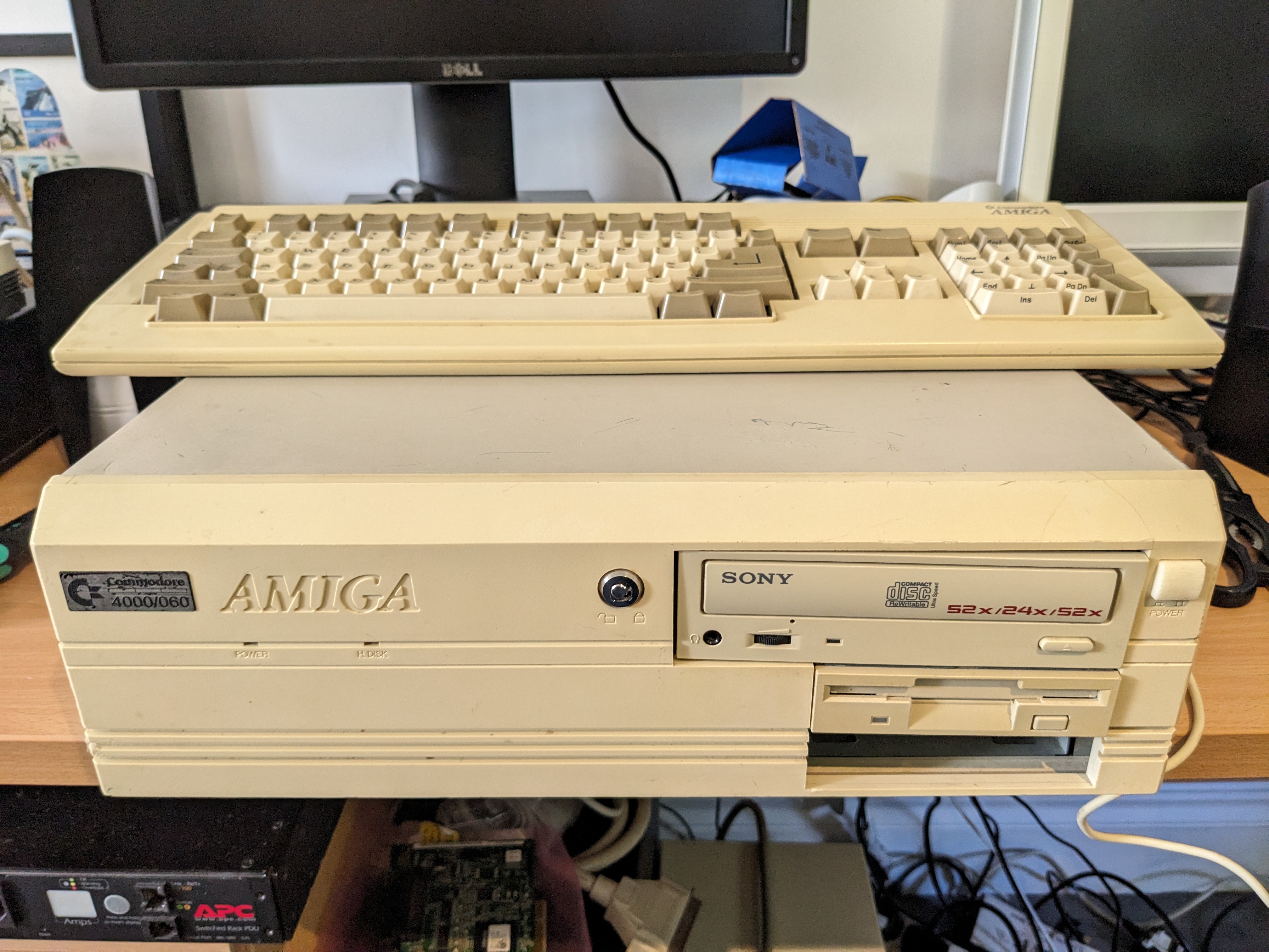
I neglected to mention in my previous post, that the 3.5″ drive bay covers were printed in a pearl white PLA. At first, I thought that the Amiga 4000 was the same colour as the Amiga 500 and 1000. But it turns out that it was a whiter colour, like the 600 and 1200. The pearl white is very close, unfortunately it is translucent, so it catches the light differently to the rest of the plastic. But it is the closest thing I had.
Finally, the lid went back on, this one is a more little scratched than the other machine, but could be a lot worse.

What’s Next?
For the new 040 machine, I might improve the cooling solution, especially for the CPU. I have a spare, unused, 486 heatsink and fan. I just need some thermal tape to mount it. The keyboard also requires cleaning, and I have a Lyra 3 (a PC PS/2 to Amiga keyboard converter) for the machine without a keyboard.
The 030 Amiga requires an OS installing. After that, and a small family holiday, I will probably sell this machine.
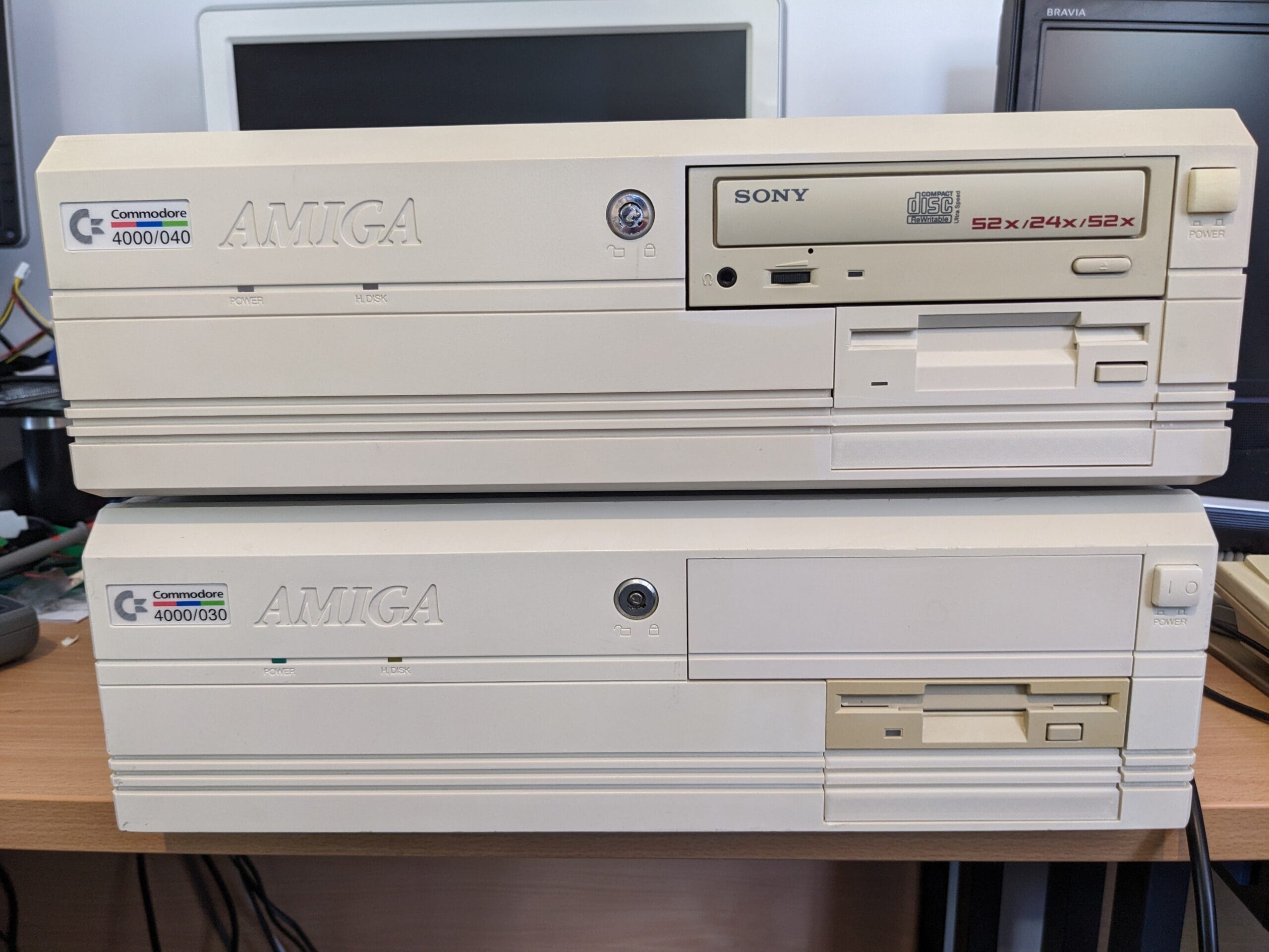
This, however, is the last restoration post for these machines. So, I leave you with a photo of the two completed machines.

Leave a Reply