

I last left the motherboard with one more repair to make. In the background, some new parts have been 3D printing, whilst others have been cleaned and retrobrighted. Let’s continue!
CF Cards Slots
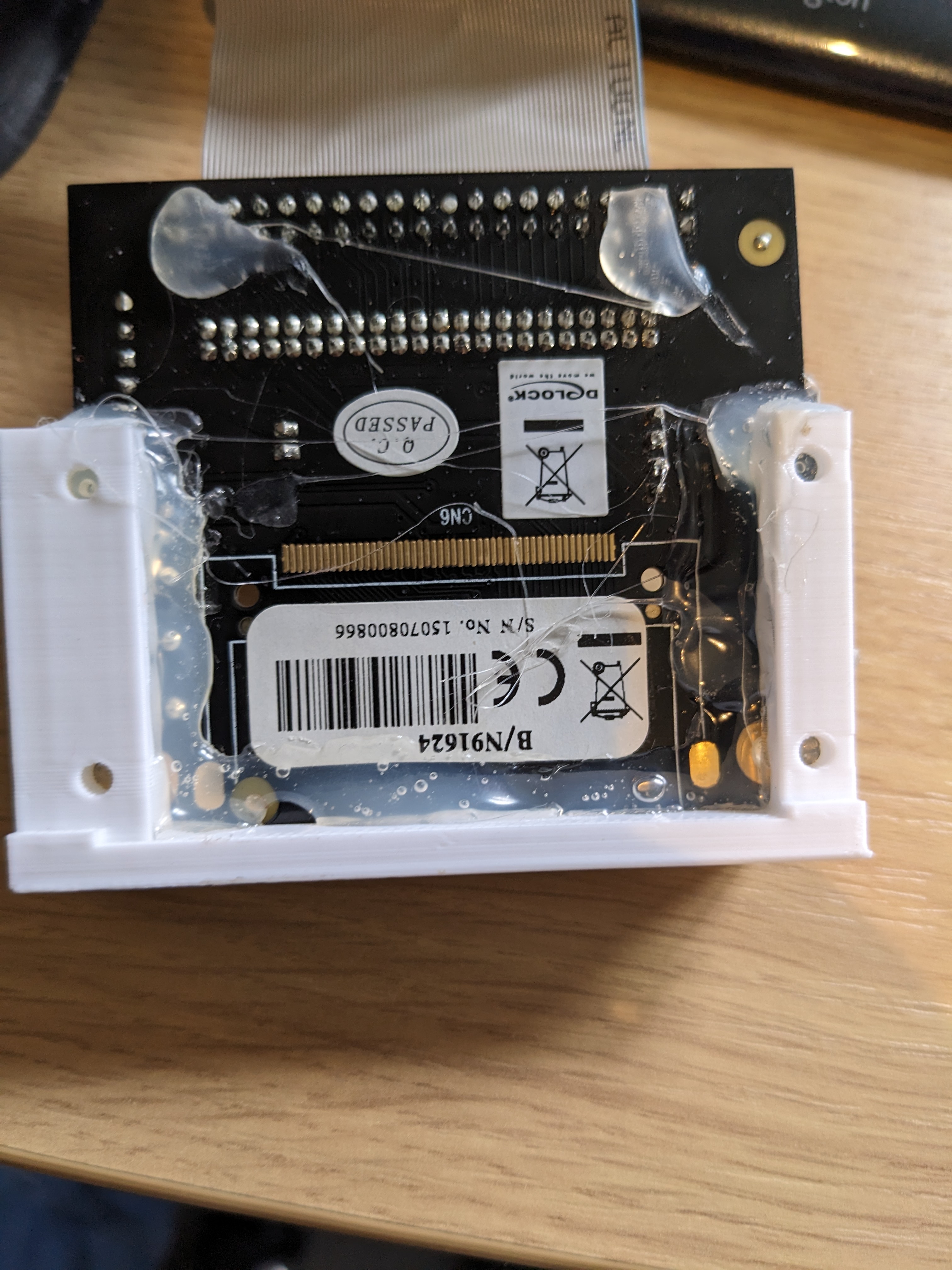
Amiga 4000 #1 came with CF card slot in a 3D printed mount for the rear of the machine. The problem is, the 3D print was for the wrong PCB, so it was hot-snot glued in-place.
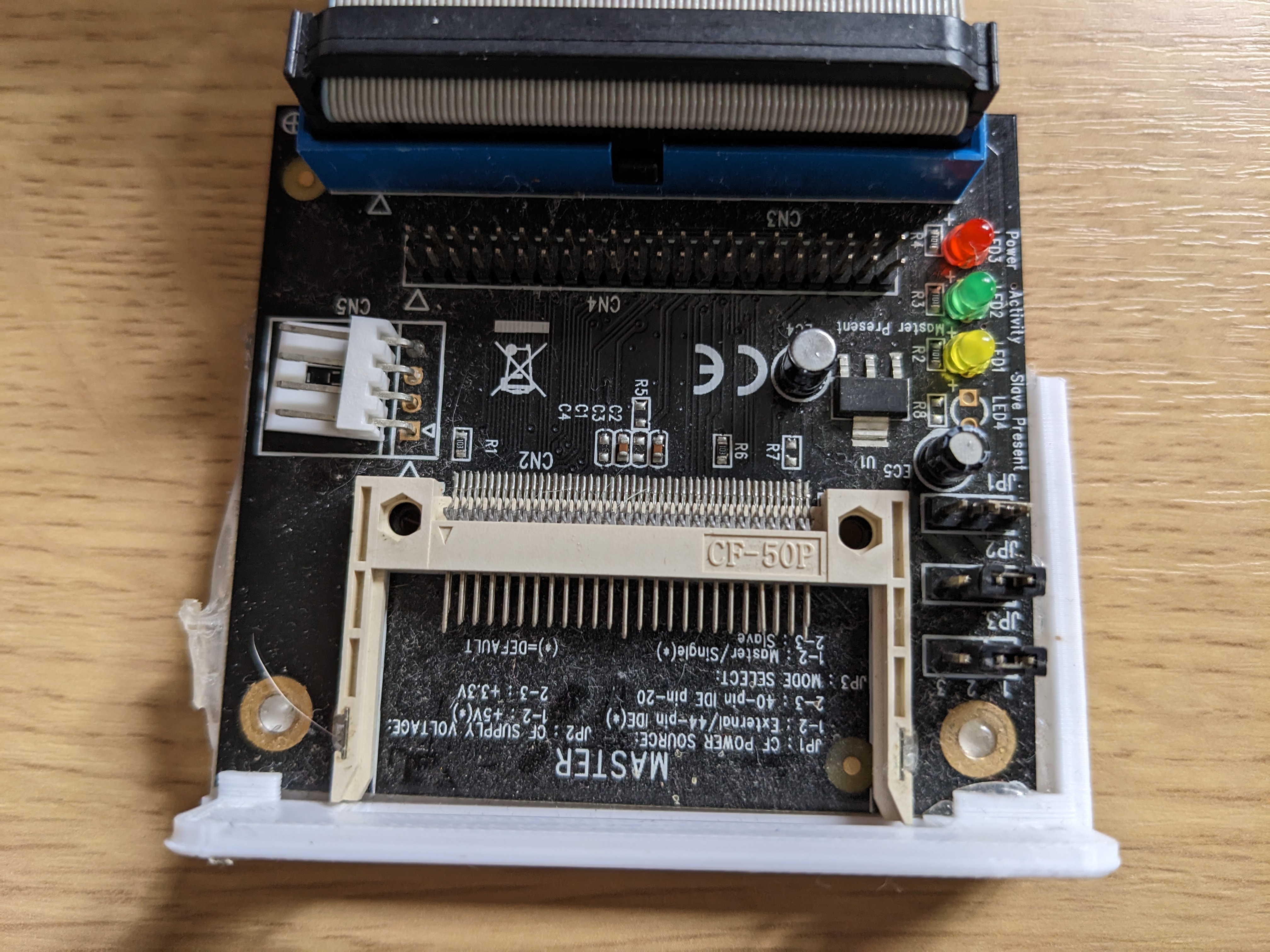
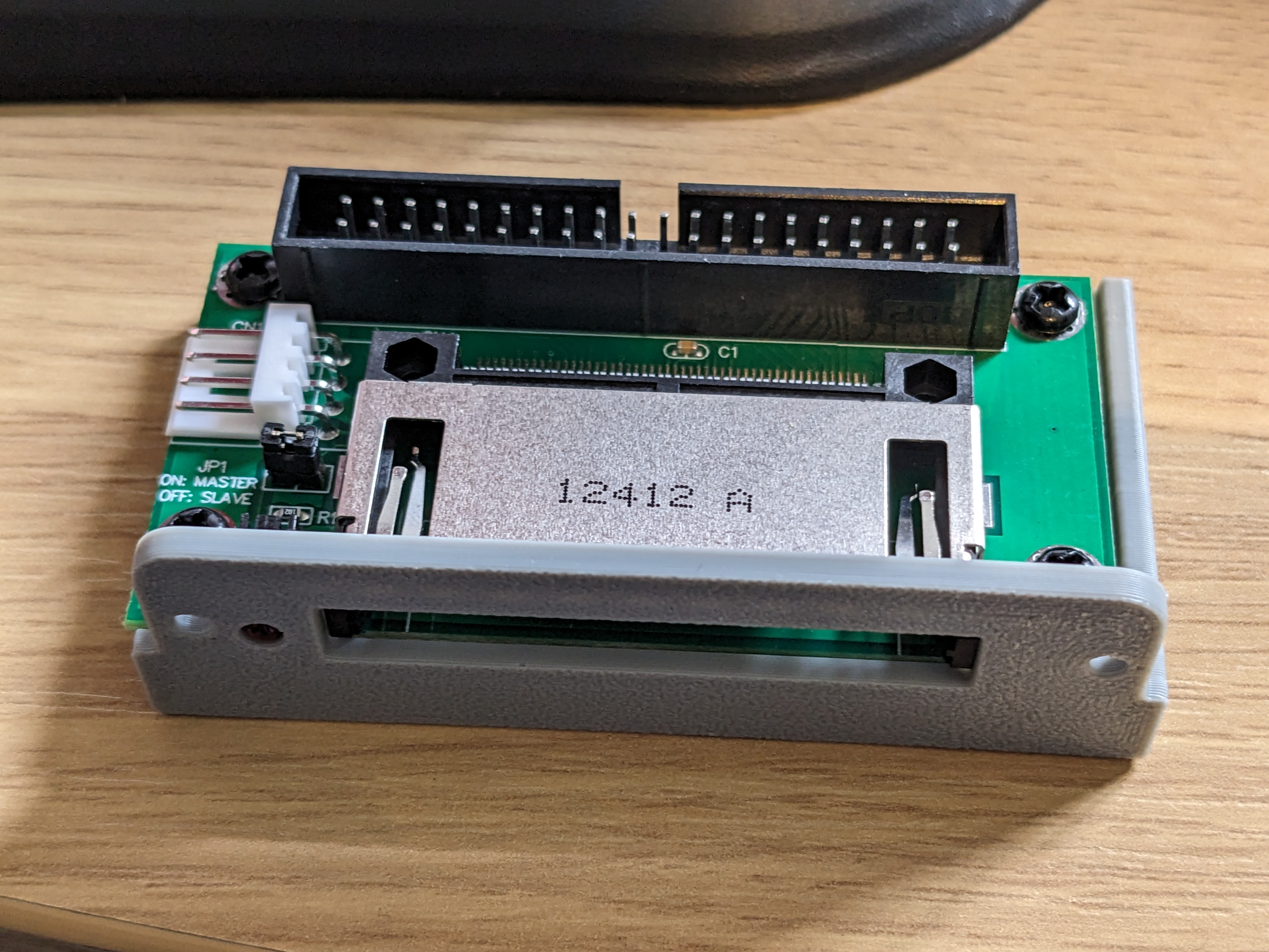
I happen to have another CF to IDE which is a better fit for this particular 3D model, but it needed a slight adjustment for the screw holes and the LED. Once measured, adjusted and printed, this looked a lot nicer.
As for the original PCB, there was an STL to fit this too. This one was designed to fit in an ISA slot. I slightly modified this too so that the top of the bracket was strengthened, and to remove a part that was not relevant for Amiga cases.
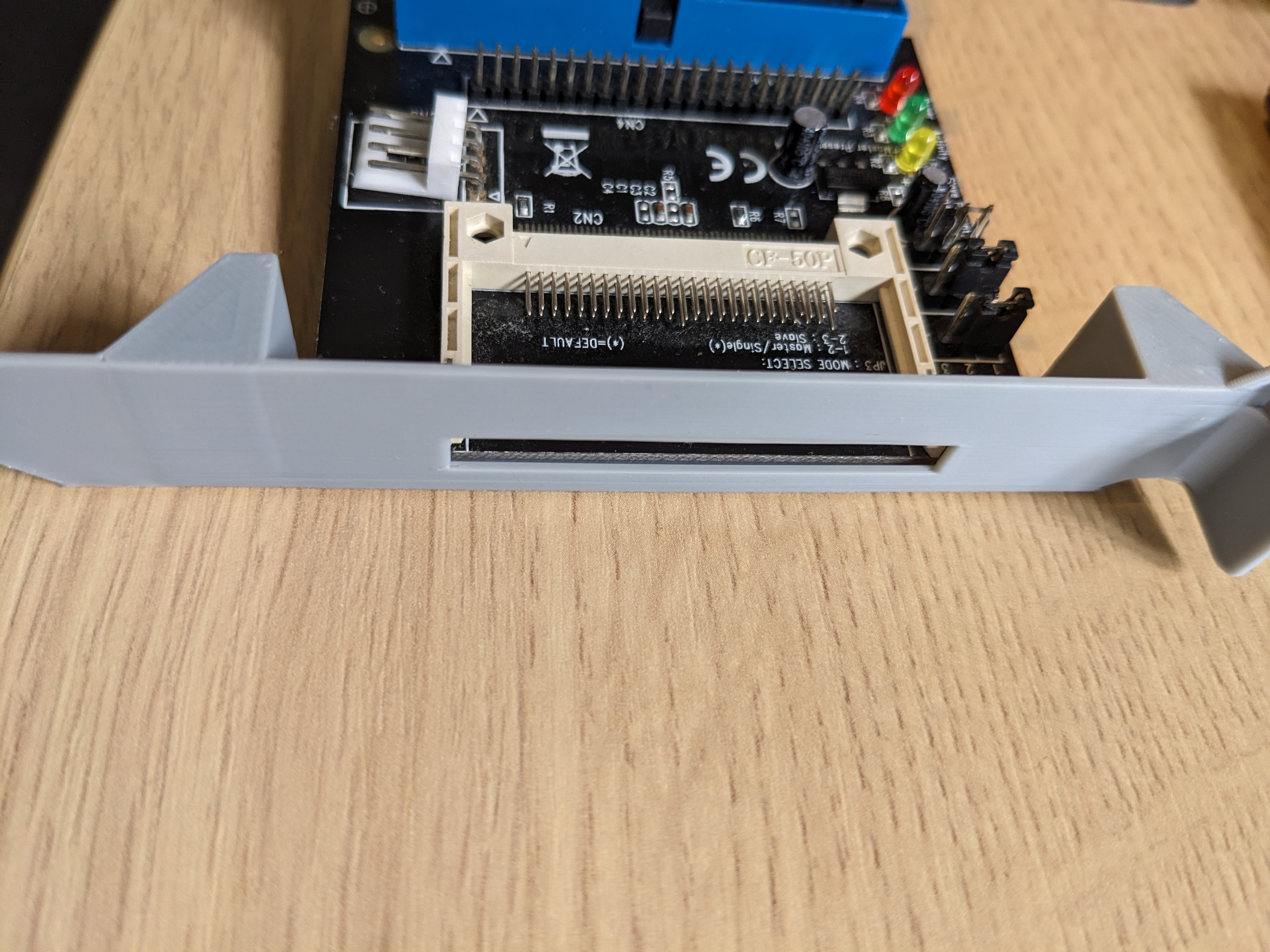
This should be good for the other Amiga.
Little Things
Two little changes were made for the mostly built Amiga 4000. Firstly, the replacement RTC chip arrived, so this was popped straight in.

The second change is a CD audio cable. The Amiga 4000 has a 3 pin header for CD audio. The pinout order is left, GND, right. Normal CD audio has two grounds in the middle, so I took a normal CD audio cable, removed one of the middle grounds and replaced it with the left audio line. The header then fitted correctly.
Retrobrighting
I cleaned the case parts with normal soap and water, removing the Amiga badges. Both were damaged, but I have a plan for that. After about 60 hours in the vapour tank in the mixed weather we have been having in the UK, the case parts came out.
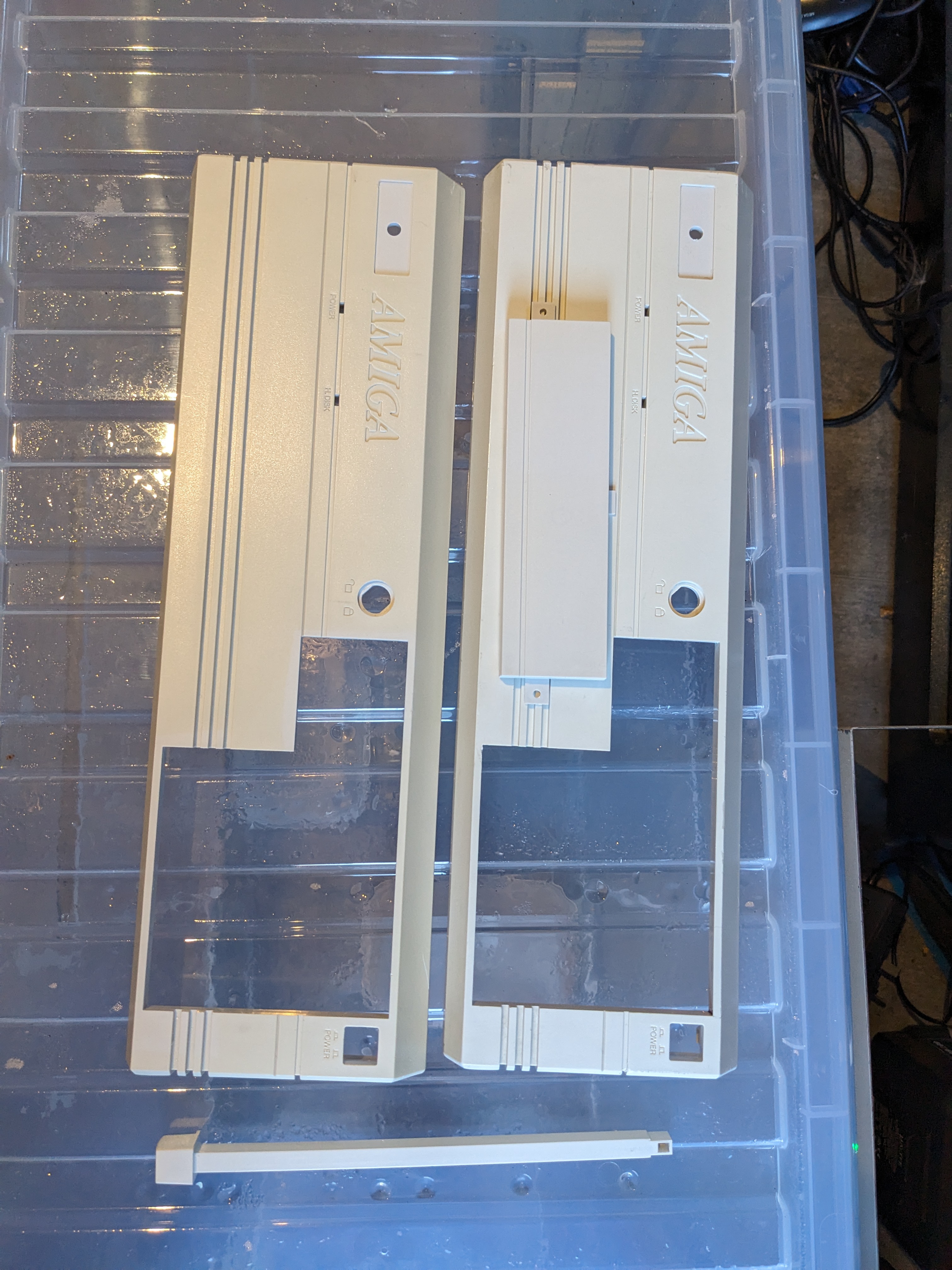
Whilst not perfect, they are a lot better than when I started.
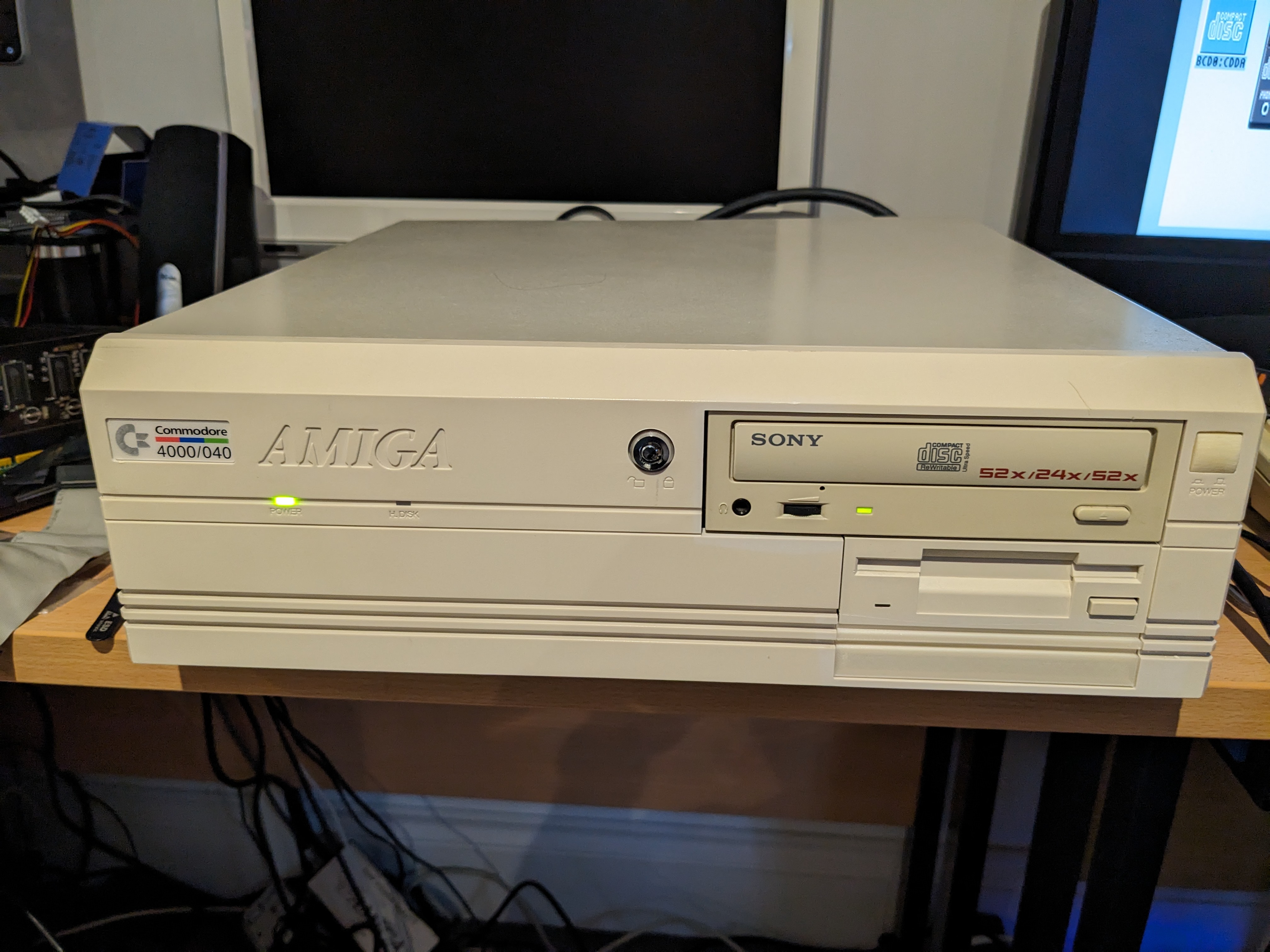
Complete Machine
Now that everything is clean I can finish the first machine. I used the lid, floppy drive and face plate from Amiga 4000 #2. The power button, CDROM and key lock came from Amiga 4000 #1. The bottom drive cover and LEDs are brand new. The new case badge comes from Retrofied, it looks and feels exactly like it should.

Those paying close attention will spot that I put the LEDs in the wrong way around (the red flashing one is in the power LED hole), I didn’t notice until after the photo, but an easy fix. It doesn’t look perfect from behind, but it is in a better state than it was.

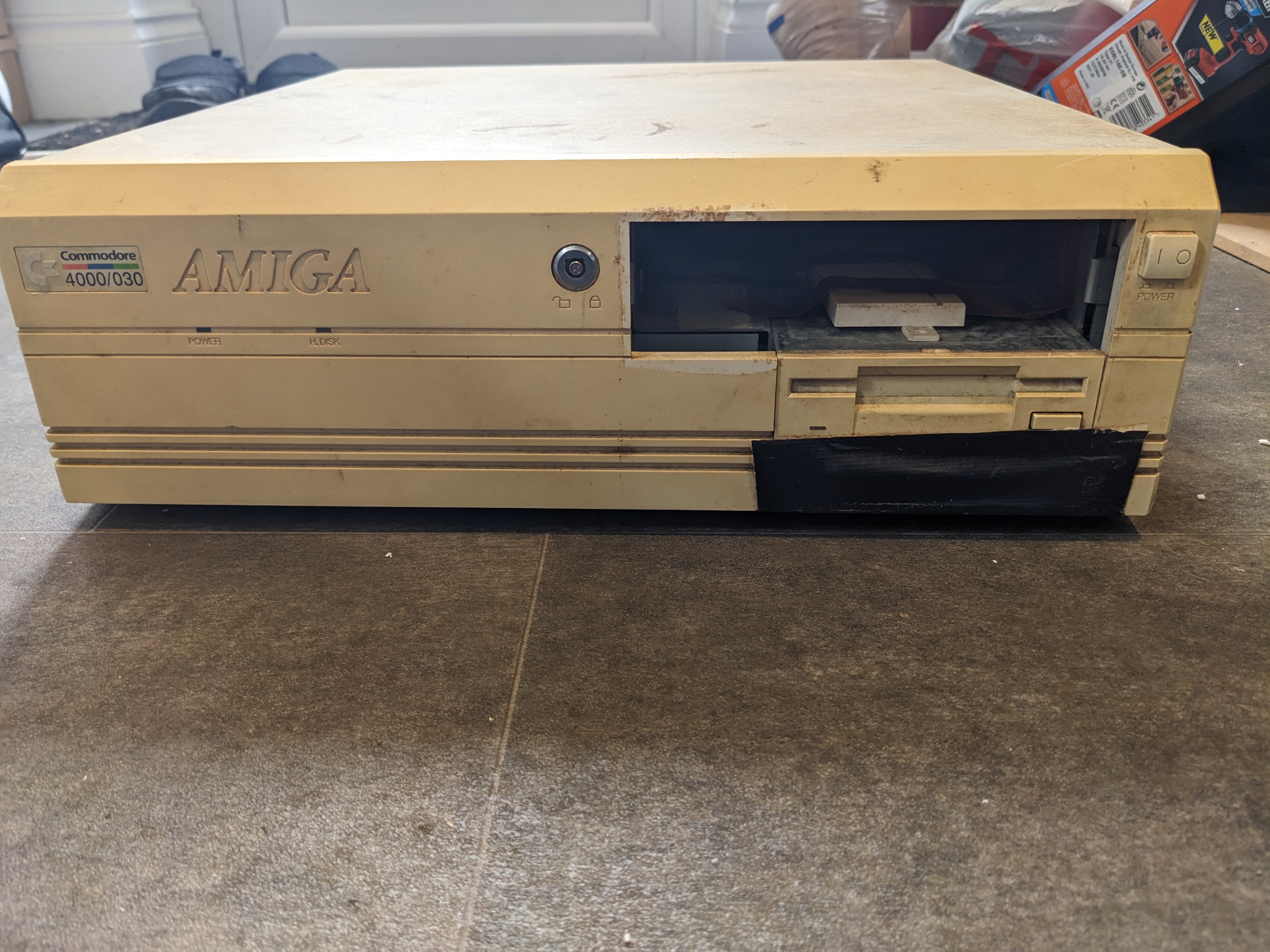
For comparison, this is what the case looked like originally.

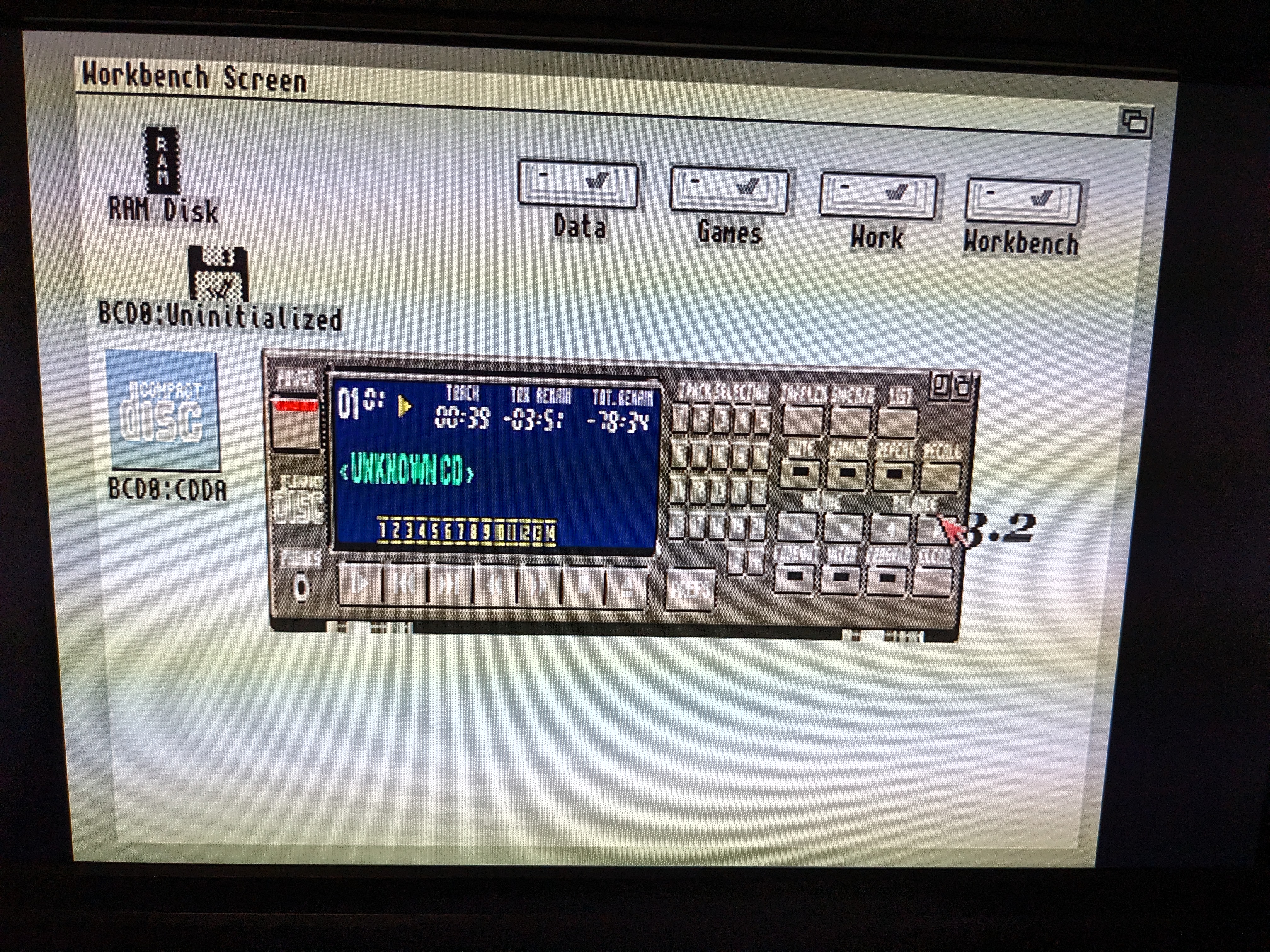
I quickly opened it up and put the LEDs in the correct holes this time. Shoved in a Guns N’ Roses Greatest Hits album and let it play!
Further IDE Diagnostics
The IDE problem on the remaining motherboard became very frustrating. At first I thought one of the GALs may be at fault, but I replaced both (and put U901 back) with no change. I then replaced U903 and U904, which are the data buffers for the IDE, no change there. When testing those chips they passed anyway.
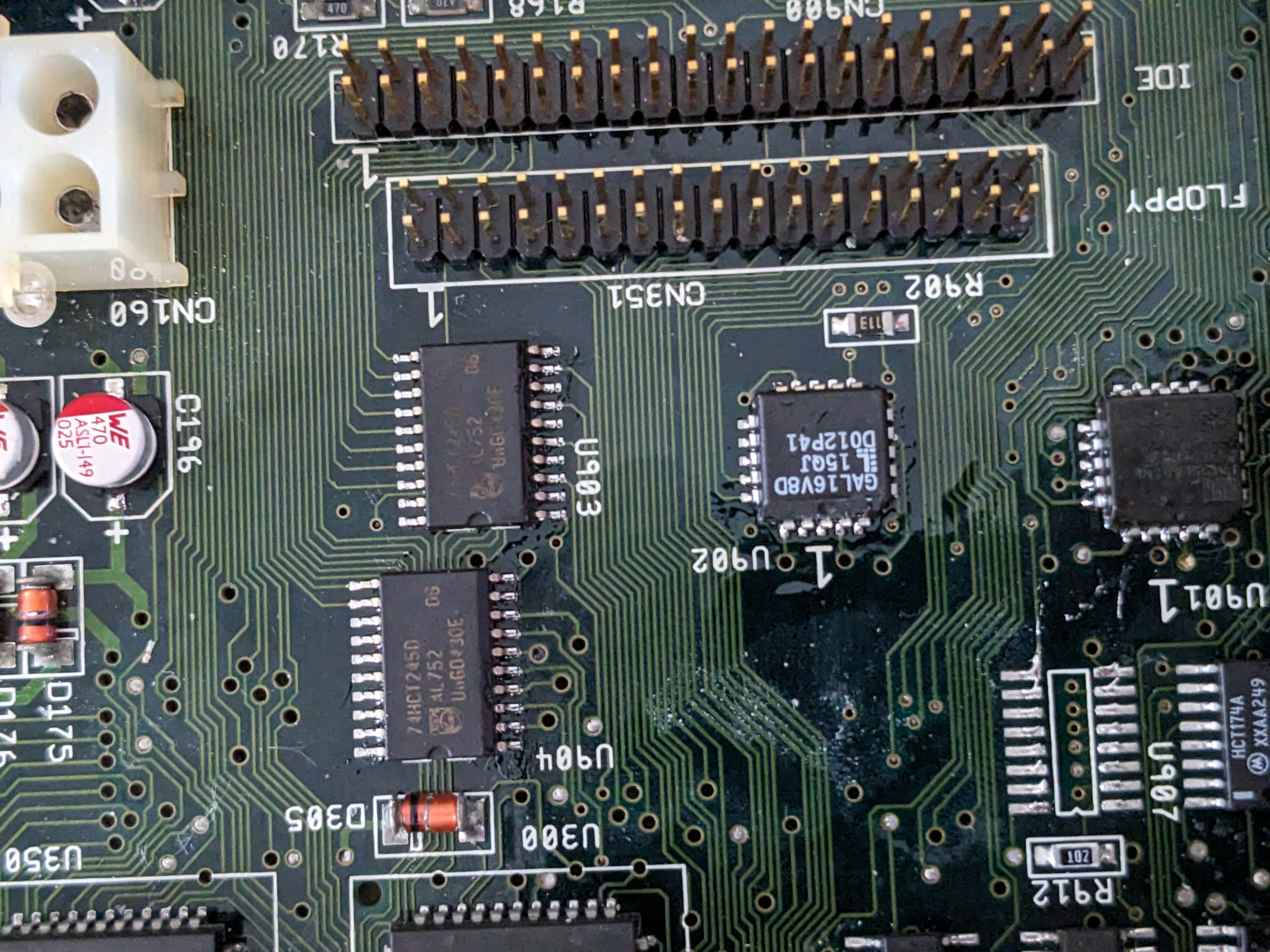
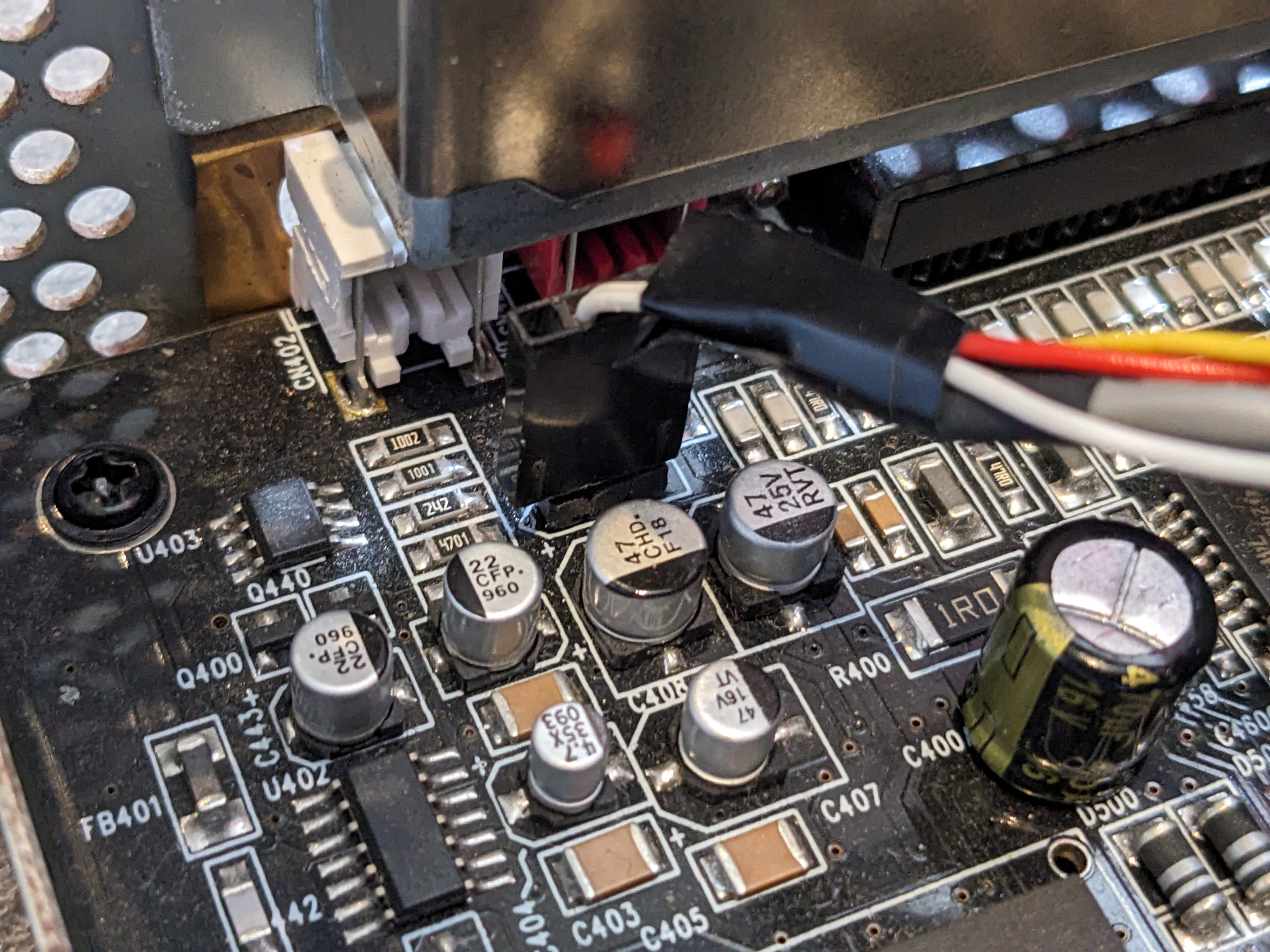
At was at this point of testing I noticed a familiar bad smell coming from the board. I turned it off, grabbed the thermal camera and turned it back on to see what was happening.
Cooking With Ceramic

Oh yes, that would do it, and that is only a few seconds after being turned on. The alignment is off on this camera right now, but it turns out a ceramic capacitor is cooking. It has started failing short-circuit. So I removed this from the board for a replacement to be fitted later. Looks like that “one more repair” I started this post with increased to two.
Back To IDE
I decided to load HDToolBox from floppy disk with a compact flash card connected to the IDE port to see what that told me about the IDE interface.
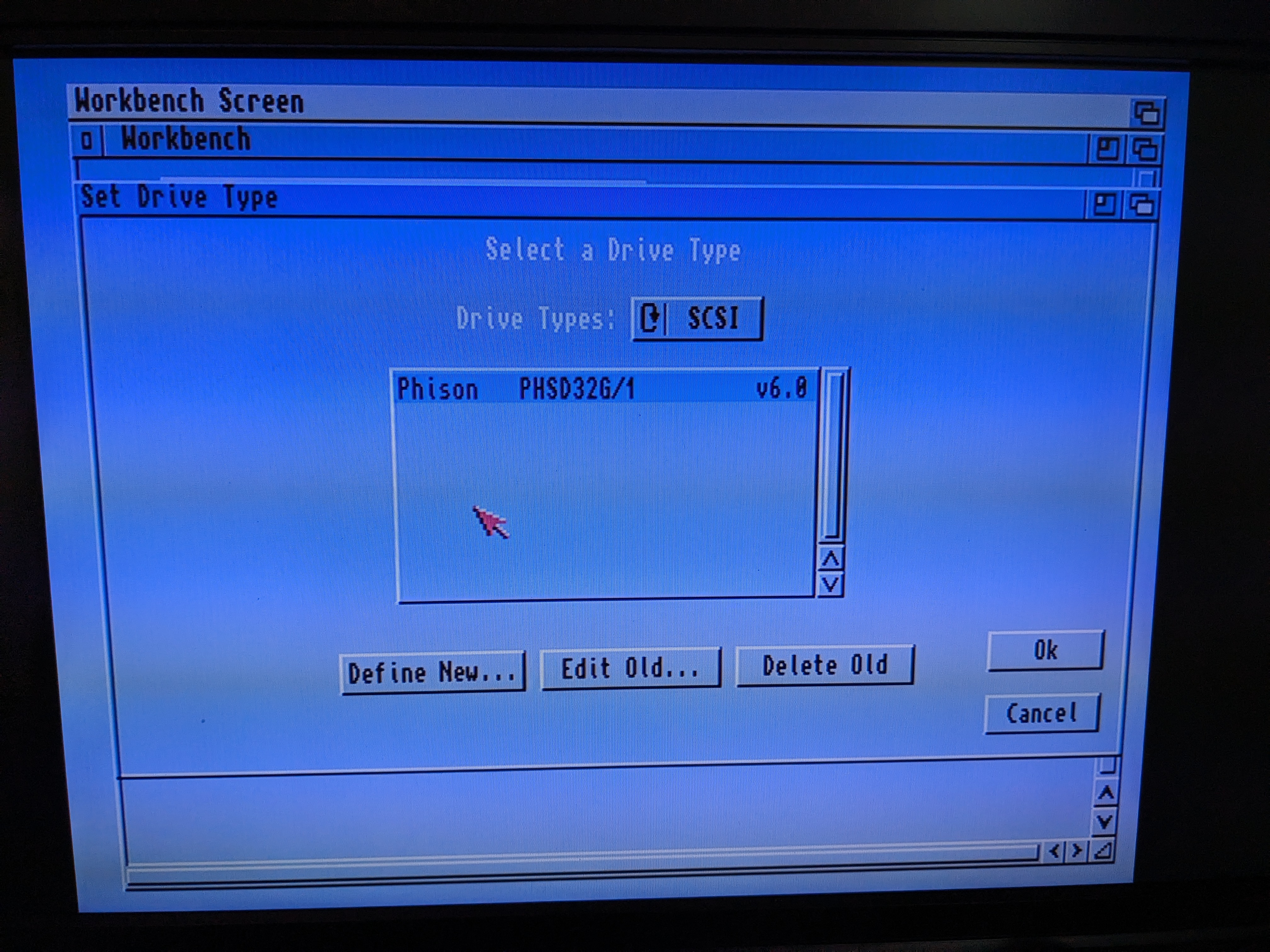

The good news is that it can see the drive exists. The bad news is it couldn’t identify it. I chatted to Peter Mullholland about this issue, and he suggested I have a look at U907. A chip that I had ignored for some reason, but it is important as it handles some of the addressing for the IDE port. With this in a bad way, it might be enough to identify the drive to some extent, but not talk to it properly.
A quick oscilloscope probe to the relevant traces below showed that things did not look quite right.
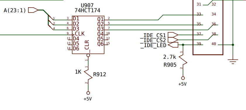
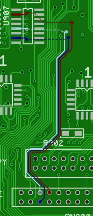
The red one in particular was being held high permanently. I desoldered this chip, soldered it to a DIP converter and ran it through the testing software on one of my EPROM programmers.
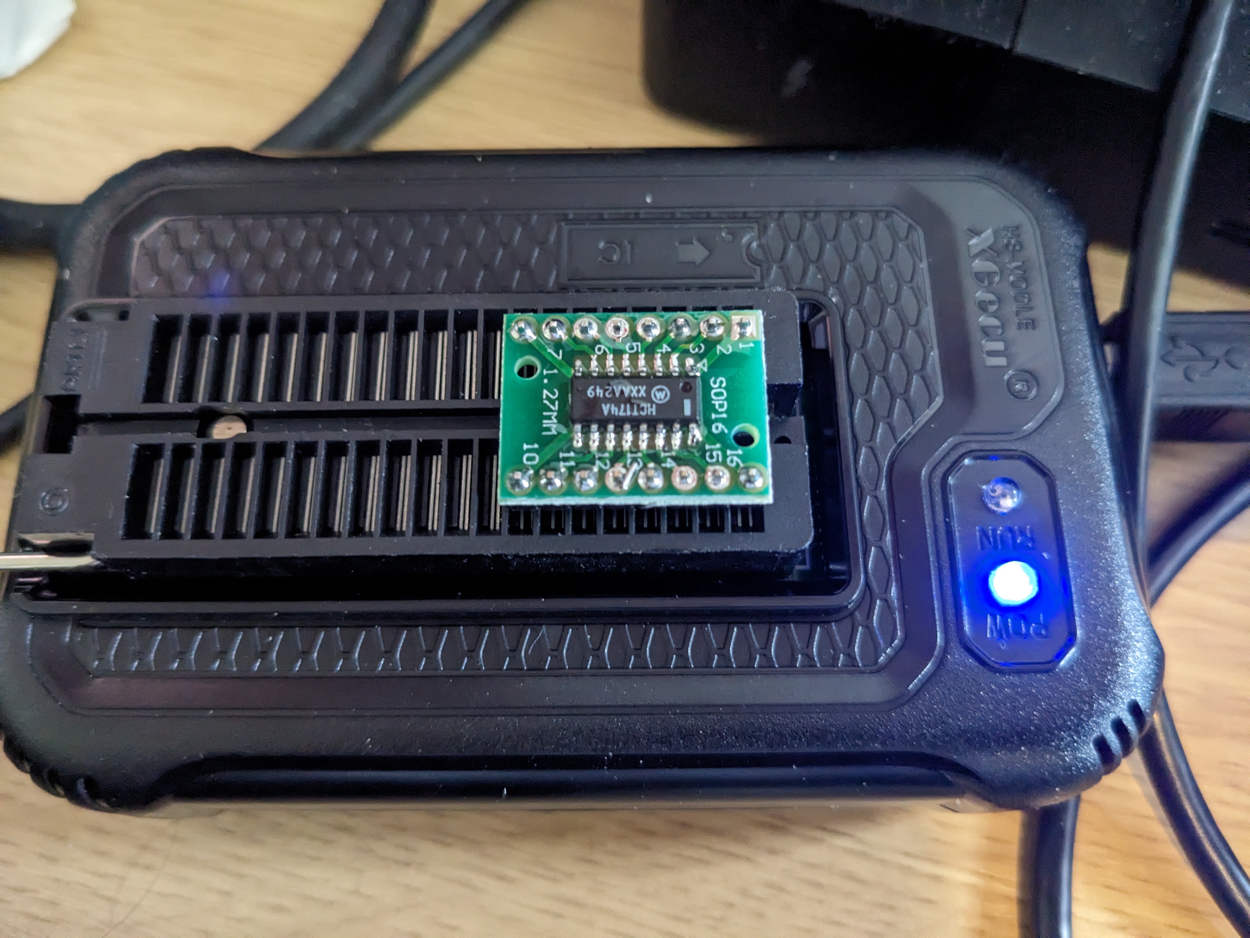
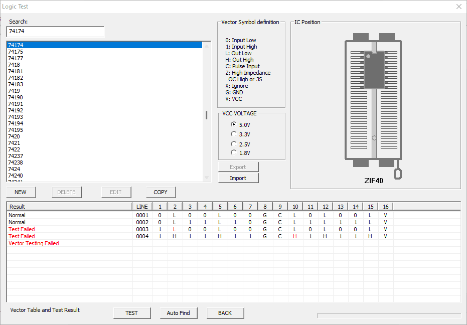
Bingo! The red ‘L’ marks a signal transition that isn’t happening correctly. The output is high instead. The pin 10 failure, whilst also not good, doesn’t matter so much. I could have temporarily wired the pin 1 and 2 I/O lines to unused pins on the chip, but I decided to replace it instead. A new one has been ordered, which means we are back to a waiting game.
Next Steps
With one machine complete, I just need to finish these final repairs to the motherboard, then I can rebuild the second machine too. I’m keeping my fingers crossed that there are no more additional repairs needed afterwards.
Leave a Reply