
We are on part 6 of what I originally hoped would be a 3 part series. There has been some progress since last time on several fronts. As well as some setbacks. Let’s get into it.
The Time Warp Again
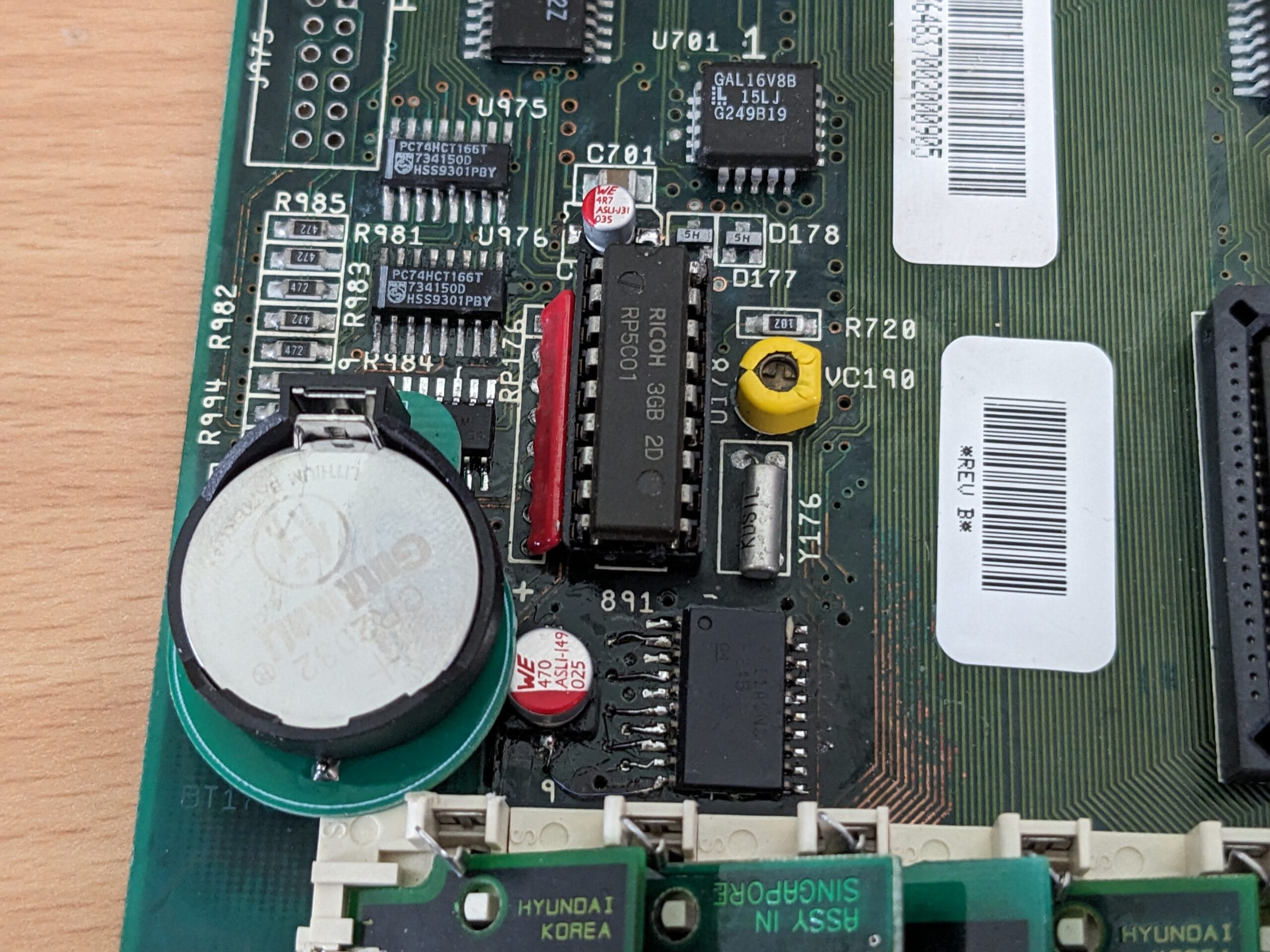
For the motherboard I am repairing, it was determined that U177 was faulty, which was stopping communications with the RTC chip. The replacement arrived, so I fitted it. I powered on the machine, loaded Amiga Test Kit, and … RTC not found.
I double-checked with an oscilloscope, and data was now getting to the RTC chip, the U177 replacement definitely worked. So, maybe the RTC itself was also faulty. Luckily, this isn’t so hard to test. I desoldered the RTC chip and put a socket in its place. On the other Amiga 4000 motherboard the chip was already socketed, so it was a case of just pulling that and putting it in this motherboard to test.


OK, that is what we want to see. The RTC chip was certainly bad, unfortunately it is incompatible with the spares I have for other Amiga models. Therefore, a new one has been ordered to put in my working motherboard.
I soldered on a spare battery mod I had available and set the clock to make sure it works with a battery.

I’ll leave it off for a while and see if keeps the time.
Keeping Cool
The modified PSU that came with the first Amiga 4000 has a loose fan in the case that wouldn’t fit. A narrower replacement arrived, so I installed it.
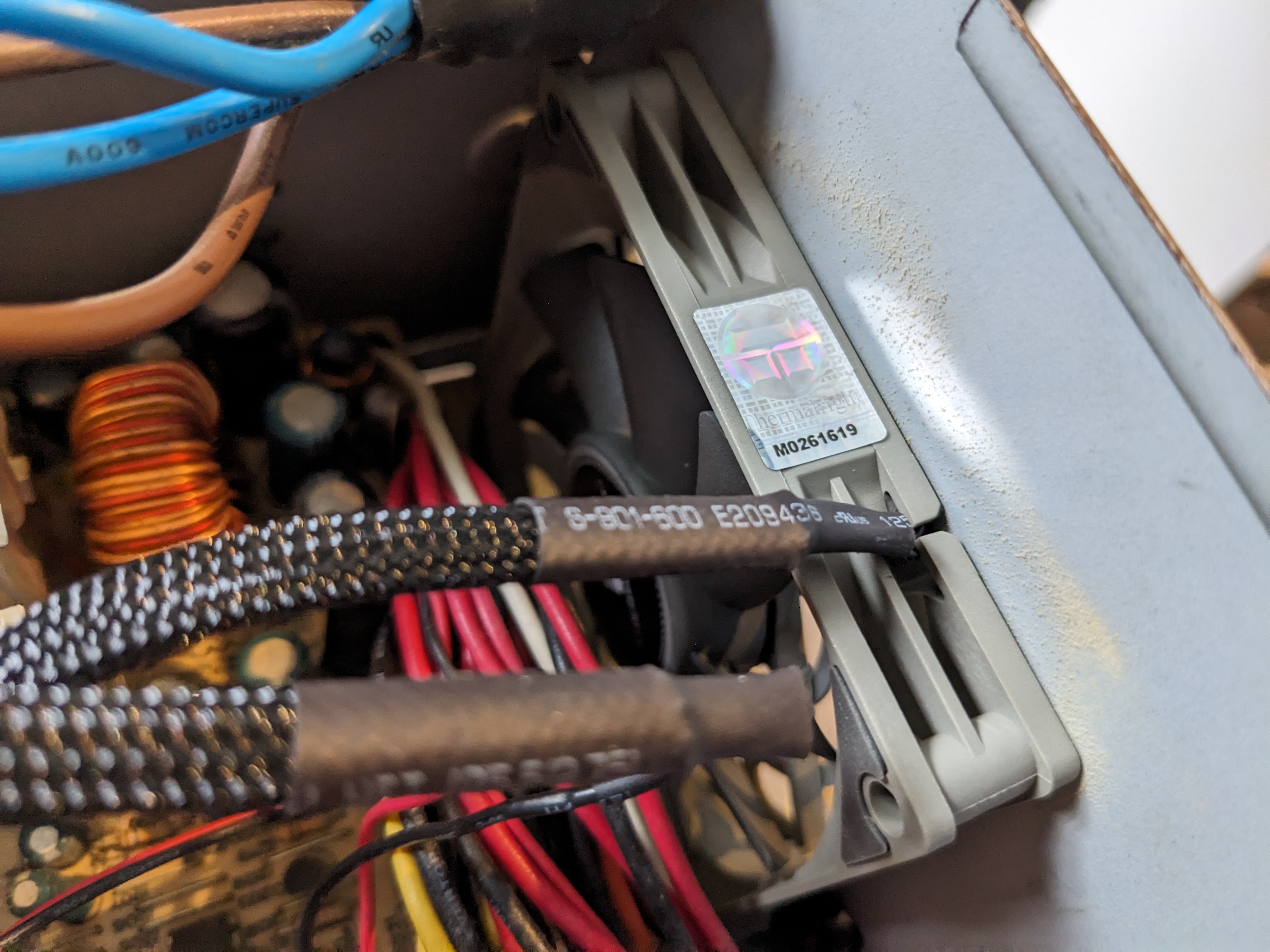

This looks a bit better. When testing this, I also checked the RTC to see if the battery was working. The fan spins up nicely and as for the RTC…

Yep, that is correct. One more thing we can consider working.
Let There Be Light
For some reason, the case LEDs in the first Amiga 4000 were something hand-cobbled together and held in with glue and tape.

I figured I would make something more like the other Amiga 4000 which uses 2 pin KK connectors for the LEDs and these fit nicely into the case, no need for glue or tape.

These tricolour LEDs will do for now, they are the right shape and are what I have in stock. I tried to test these on the motherboard. The power LED worked perfectly. To test the HDD LED I needed to hook up a hard drive. So, I hooked up the CF card hard drive from the other Amiga.
And it didn’t work.
I don’t mean the LED didn’t work, I mean the IDE interface on the motherboard isn’t working. Yet another problem.
IDE Woes
I probed around the IDE interface and related ICs with a multimeter in continuity mode. Everything seemed to be hooked up correctly. After probing further with an oscilloscope, this appears to be the real issue.

This trace is a signal from the programmable logic chip in U901 that enables the other three chips when signals are coming for the IDE, it is supposed to go low to enable them. This signal is stays high permanently. So, my current working theory is that this chip is bad. I’ve ordered a replacement to program and luckily the firmware for it is readily available.
Filthy Floppy
The floppy drive in Amiga 4000 #2 was quite dirty, and it had duct tape across it, like other parts of the machine.

The faceplate and button have been removed for cleaning and retrobrighting. Meanwhile, I decided to see if I could get the drive working. It was extremely dusty inside, so I cleaned it out ready to test.

Not perfect, but you should see how much came out of it.
In the Amiga 4000 I booted Amiga Test Kit using this drive and ran the floppy drive test.

Actually, pretty good, if I recall correctly, that ‘B’ marker is actually a fault with this particular disk.
Cleaning and Brighting
The plastics on both the machines have been removed ready for cleaning and retrobrighting. The cleaning process was tricky because someone appeared to have used duct tape on the second Amiga 4000. I’ll show the results of that when the retrobrighting is done.
I also cleaned the top of the second Amiga 4000. This is a before and after shot.


It is certainly looking a lot better. Not perfect, not certainly more acceptable.
I also modified the standard STL for the power button and rod, adding a 0 and 1 on it, similar to the original power button, but larger and more defined. This was then printed in Jessie filament. It’s not perfect, but I like it.
Final Steps?
I think all that is left is to fix the IDE on the motherboard I’ve been repairing, replace the missing RTC from the good machine, and finish the cleaning and brightening. But I would rather not tempt fate right now. The brightening will take a few days, so I will report back when that is complete.
Leave a Reply