
In part 4, I had the motherboard for the Amiga 4000 #2 mostly working. But it required a new buffer chip for the Fast RAM. That chip arrived, so let’s continue…
U891
This chip has been such a pain, it is going to get its own title. The new chip arrived, and I soldered it on, adding patch wires for the missing pads. At first, it failed in exactly the same way as before. I then found the cause, the ground to that area had been damaged, the electrolytic cap near it also had no ground. Reattaching the ground finally got DiagROM to boot properly. The Fast RAM did not show up, but I could force test it to find out why.


Two bits were consistently failing, both controlled by U891, that is a good start. It turns out the leg for bit 0 was not soldered properly on the bus side and the patch wire for bit 4 was not attached to the leg properly on the RAM side.
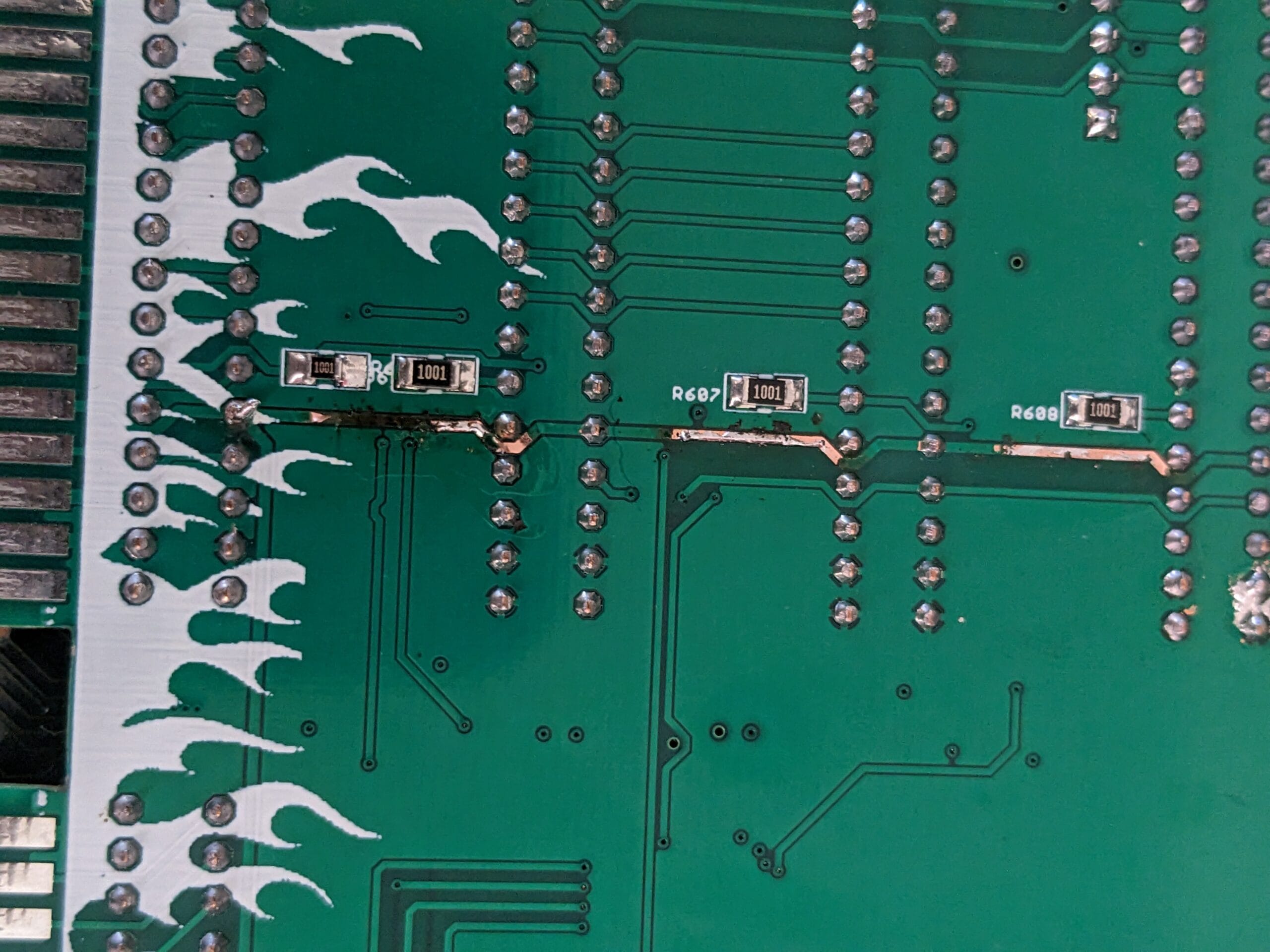
When booting DiagROM again the RAM was detected properly (kBFast in the first image below) and I could run a full test on it.


Amiga Test Kit
Now that DiagROM is passing in key areas, I decided to put the original Kickstart ROMs back in and attempted booting Amiga Test Kit from a GoFloppy drive.

This is a good sign. I ran a few tests from this.


Gah! “No Clock Detected”?! The RTC clock chip is what the battery powers when the machine is off, and this means there is damage I haven’t spotted yet. Here we go again…
The Time Machine
I buzzed around the area with a continuity tester and confirmed my initial findings that the connections to all the ICs are fine. I then tested the resistor pack next to the RTC and found a problem. The resistor pack provides a 10K pull-up to several of the RTC data lines, and it looked like one of the resistors had failed. It was only reading as 0.5K, which will make the pull high far too strong. I confirmed with an oscilloscope that this line is being held high the whole time the machine is on.


This red line here is the trace that is affected, RP176 is the resistor pack. Unfortunately, I did not have a spare, but I do have an Amiga 2000 motherboard that has one, and I removed it from there until I can get another one.
This made no difference, so there is a issue somewhere else that is causing the low resistance. That trace is only connected to U177 (a flip-flop chip) and U178 (the RTC chip). I removed the RTC chip first and added a socket.

The problem was still there without that chip. Which leads me to believe the fault is with U177. When removing this, the resistance was back to the normal 10K. Which meant I had to order in another chip and wait for delivery.
Rebuild A Machine
As mentioned in my previous post that I’ll be replacing the failed PSU with a new one based on this post. The first step is to 3D print the mount for the PSU. It came out quite well, but I didn’t have things quite dialled in correctly, so two of the corners lifted quite a bit.

Using this, I was able to rebuild the machine. I used the frame from Amiga #2, cleaning it as I assembled. The motherboard daughterboard and drives came from Amiga #1.


I reused the Buddha IDE from my Amiga 3000 build in this machine to drive the CDROM. I was told by the original owner of machine #1 that there were stability issues when the CF card and CDROM were both running from the onboard IDE. So, this made a nice solution to that problem.
Powering Up
Once it was all assembled, I powered up the machine. Immediately, it let out the magic smoke. Not a great sign. I looked to me like the smoke was coming from this regulator:

The regulator is unused on this board because the CPU is a 5v 68040. So, I removed it and directly wired the jumper instead.

But it turns out, that is not what let out the smoke. When powering it on again, the smell continued. I discovered that the crossbar support for the case was shorting out on this berg connector.

This actually caused the 12v line to burn up.

This is what was really smoking. It turns out that this is a known issue with this reproduction daughterboard, and has been for three years. To date, nobody has fixed it.
For now, I have removed that and installed the A4000 #2 daughterboard. The machine works correctly with both daughterboards. But the one from A4000 #1 has no working 12v rail until I repair it.


I still need to work on the face of this machine, but we are close to having one machine completely built and functional. The work on the other motherboard continues!


Leave a Reply