

Following on from my previous BBC Micro restoration post, I figured I should take a look at BBC Micro #2. Let’s see where we are at.
Powering Up
I have a USB-C power supply for a BBC Micro, which makes things easier for testing. Especially since I know I’ll need to refurbish the power supply. I know from the person I acquired it from that it was not working. So, let’s see what happens.
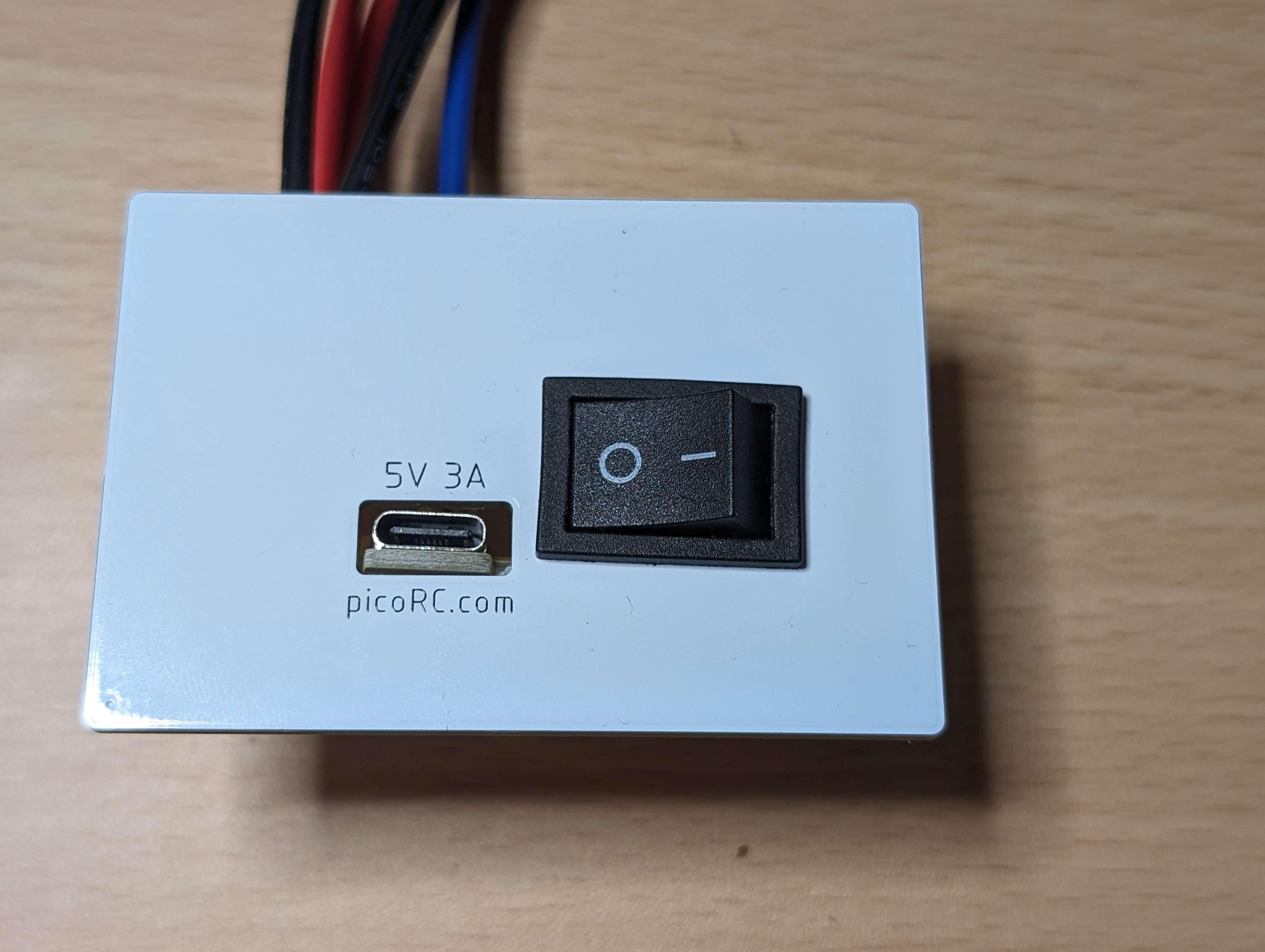

Flicking the switch, I heard a never ending “Beeeeeeeee” from the speaker and no output on the video. Definitely faulty.
Diagnosis
OK, let’s start with things that can definitely go bad. I tested the CPU and the two 6522 chips in my Backbit Chip Tester which I showed in this post. These were all fine, as was the one socketed logic chip and ROMs. I also swapped the video chip and video ULA with my working BBC B, just to check those. They were all good.
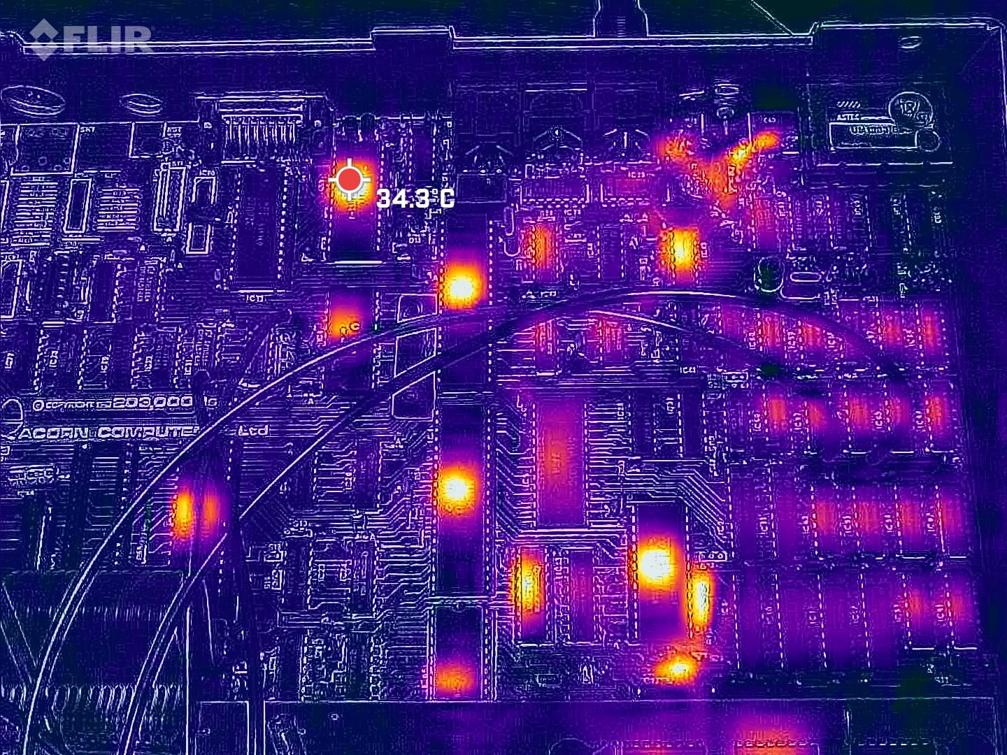
I then checked the thermals for the motherboard to see if anything was getting obviously too hot. All looked normal.
Next is a little trick I discovered. There is jumper S25, this determines how much RAM is in the system. BBC Micro model A has this set to south (Acorn uses compass directions for jumper positions) to address 16K of RAM, model B has it set north to address 32K of RAM. So, if I set this south, half the RAM is disabled. I’m suspecting the RAM is the issue anyway.
I powered this up and I got… something…
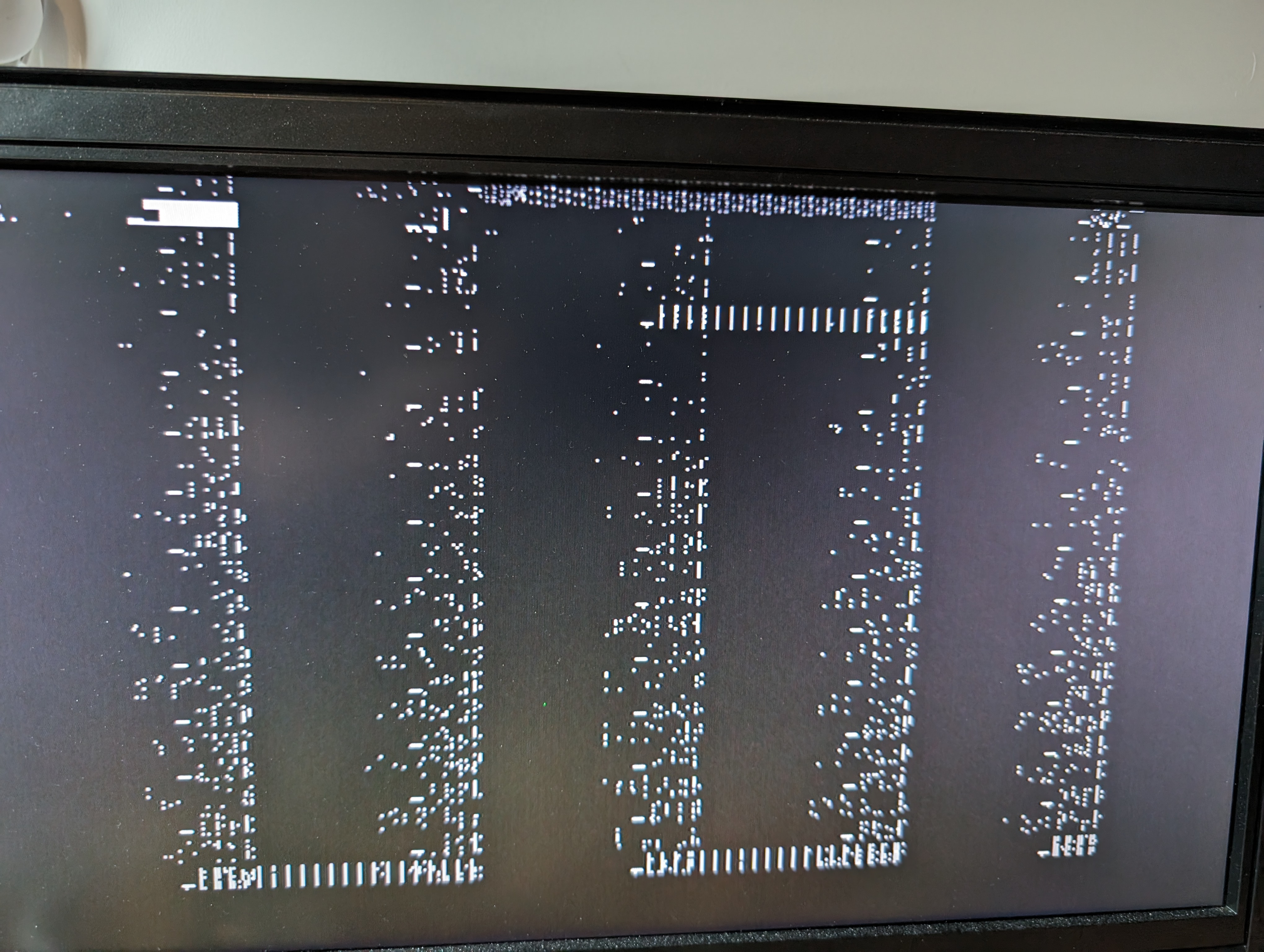
Extremely likely the RAM is bad then. There are 16 RAM chips in the BBC Micro B, and they are all soldered in. This is going to be a lot of work, even for my Hakko FR-410.
RAM Testing
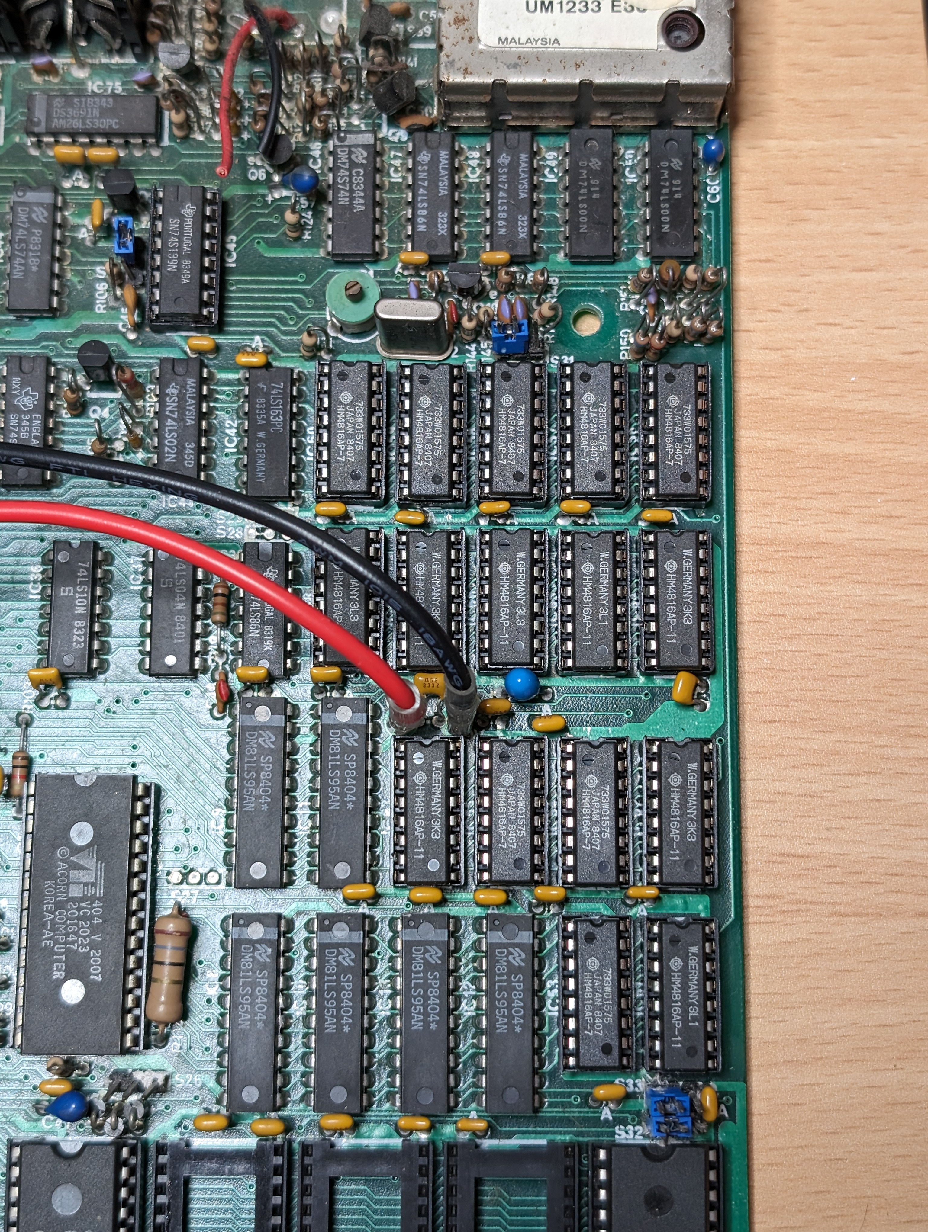
Time to desolder all the RAM chips and test them. Here is the RAM area of the motherboard.
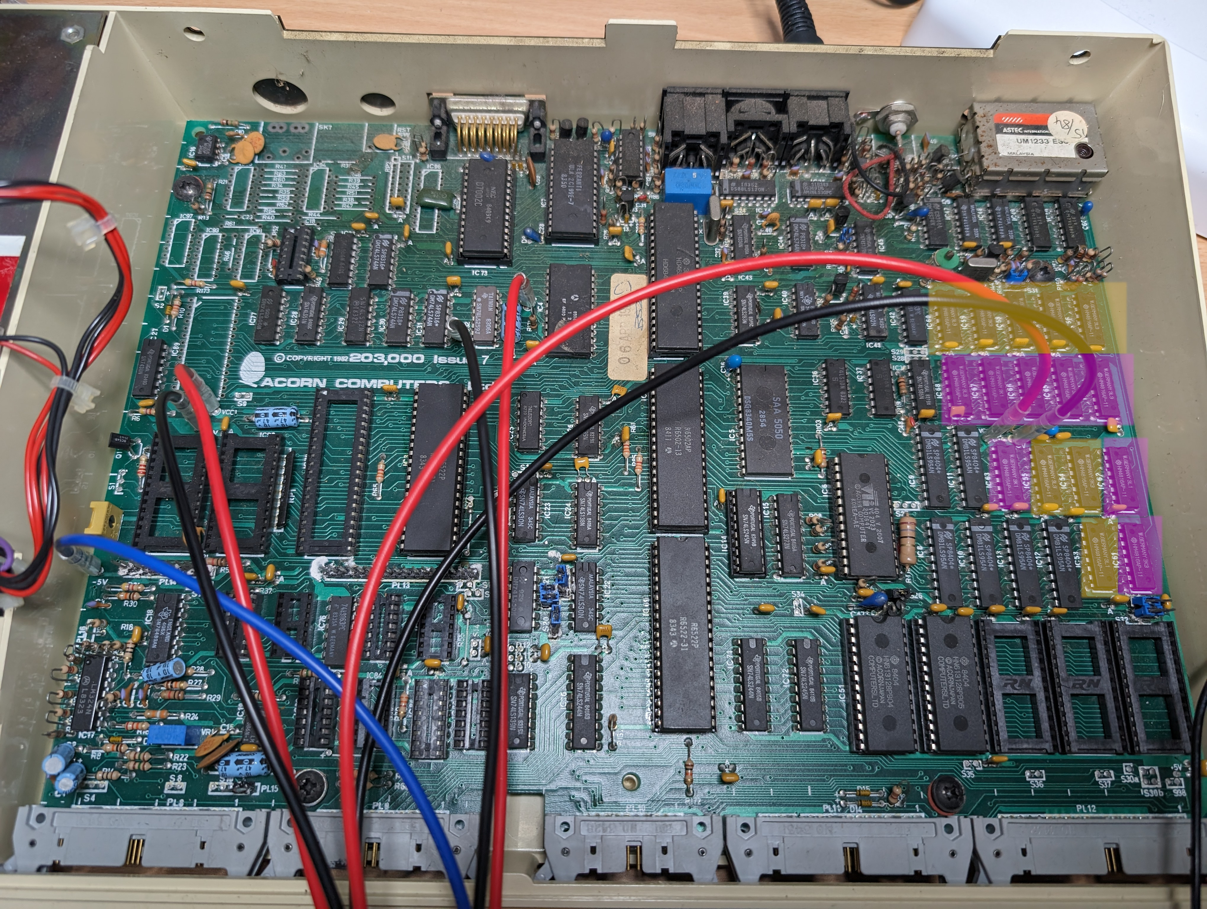
Yellow is the bottom 16K of the RAM, used in a BBC Model A and purple is the top 16K which is in a BBC Model B (or an upgraded model A).
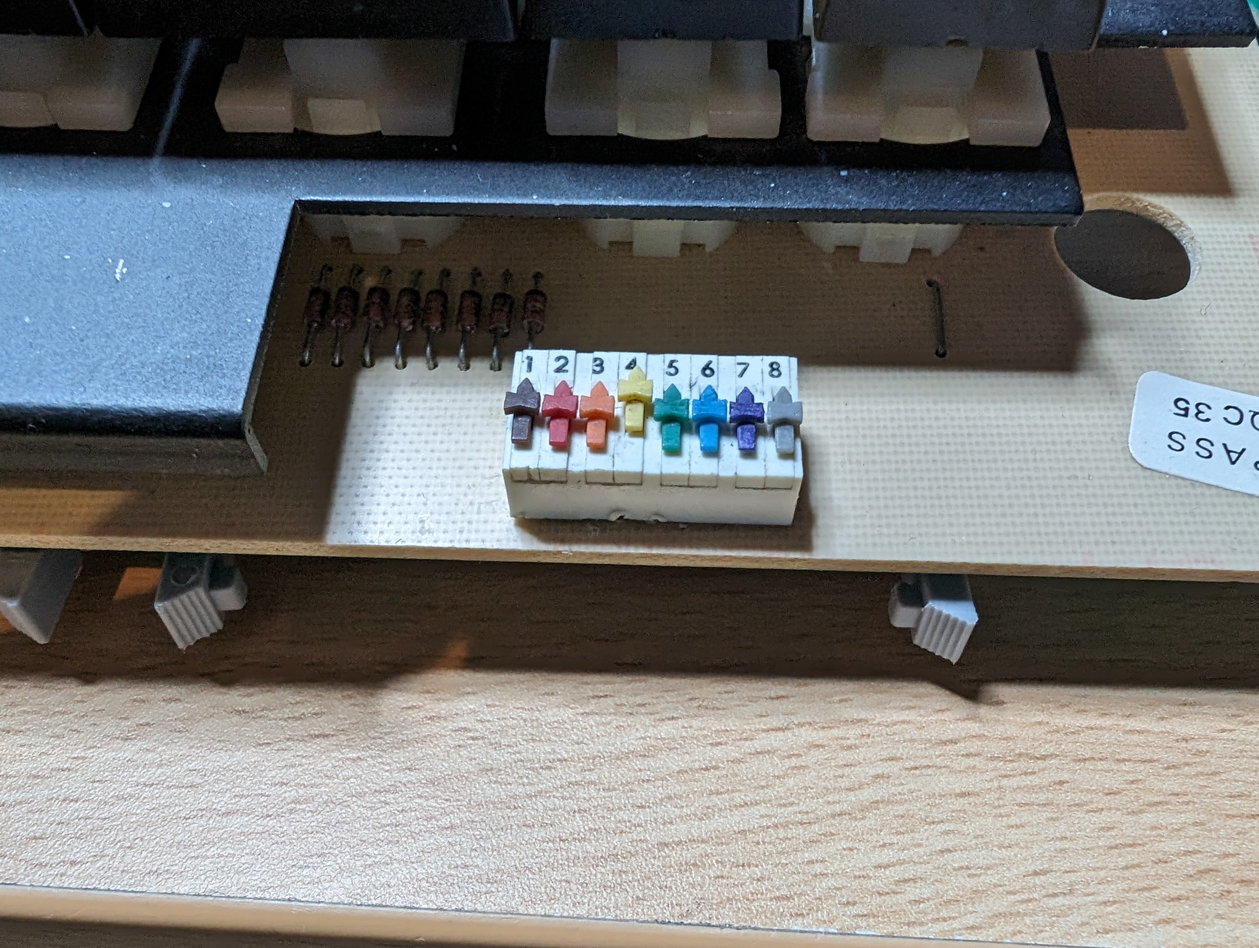
After all the RAM was desoldered, I ran it through the chip tester and one chip failed.
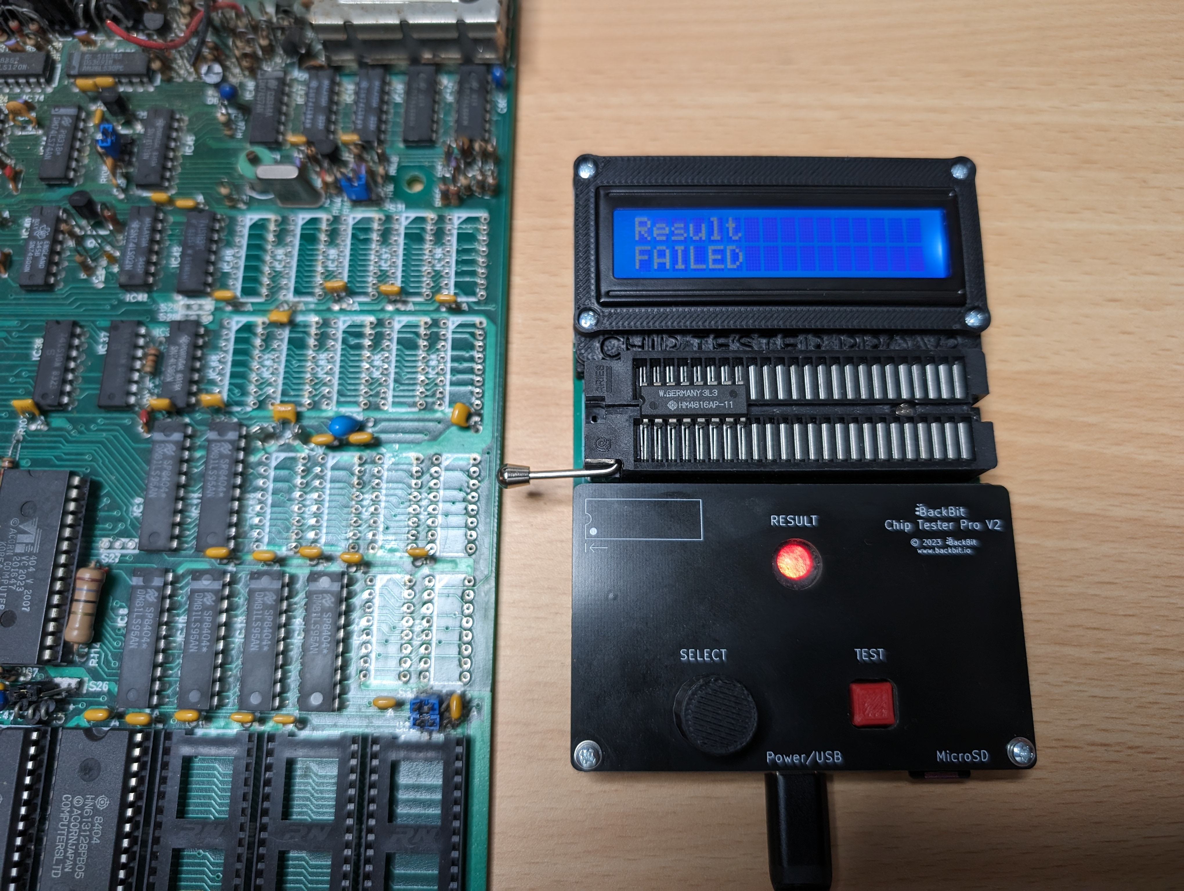
This chip came from the second row of RAM, which is part of the top 16K. This had me a little concerned that something else is wrong, but maybe it wedged something on the bus.
Next, I put sockets in place for the RAM and popped in enough to boot it as a model A.

I powered this on and…
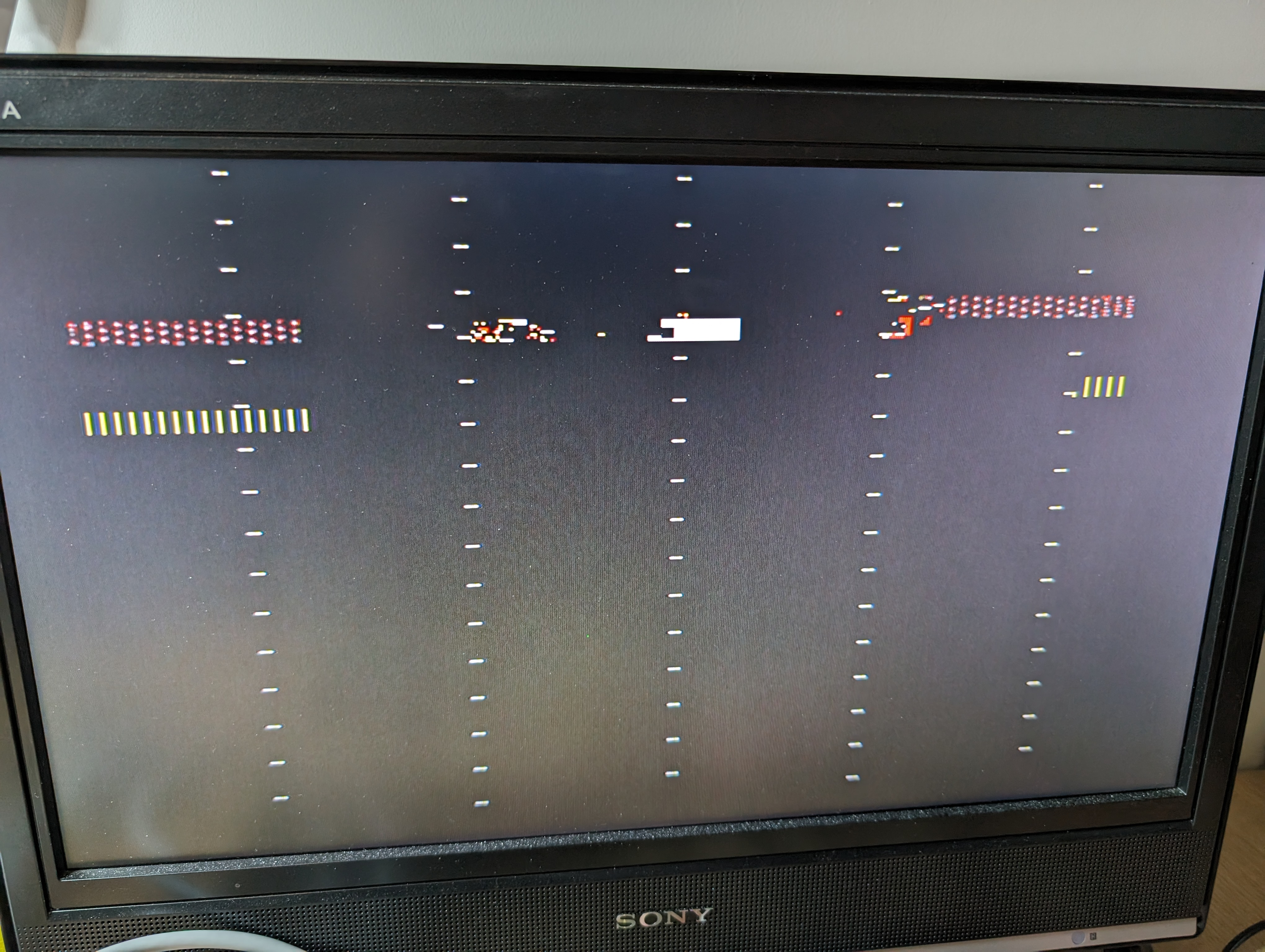
Damn…
Further Testing
I first pulled the teletext chip (SAA5050), in case that was causing issues, as long as you boot into something other than mode 7, this will work fine. You can change the bootup mode with dip switches on the keyboard.
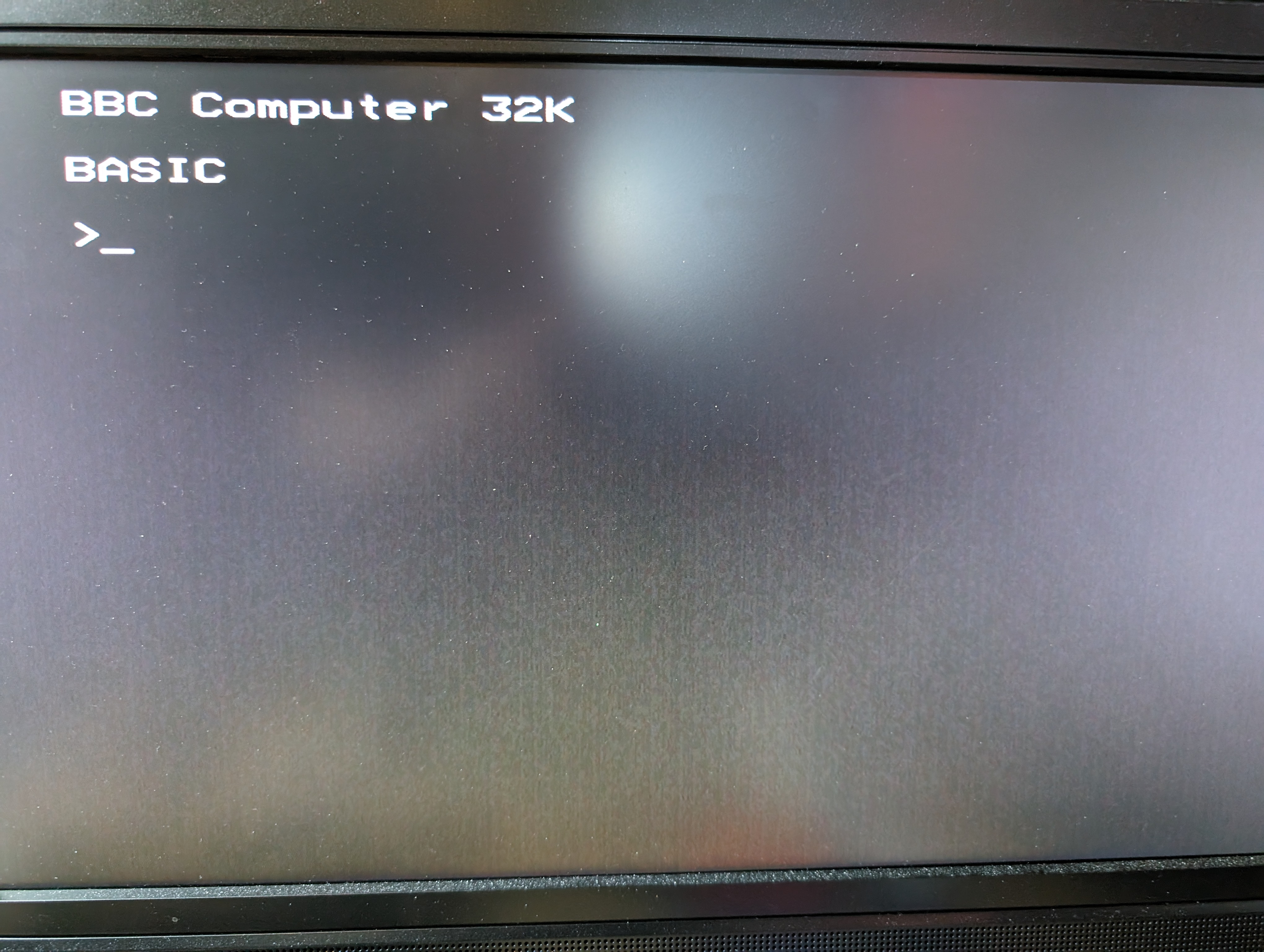
This didn’t work, but interestingly, changing the mode to mode 4, I did get somewhere. This is set by popping the last two switches up.
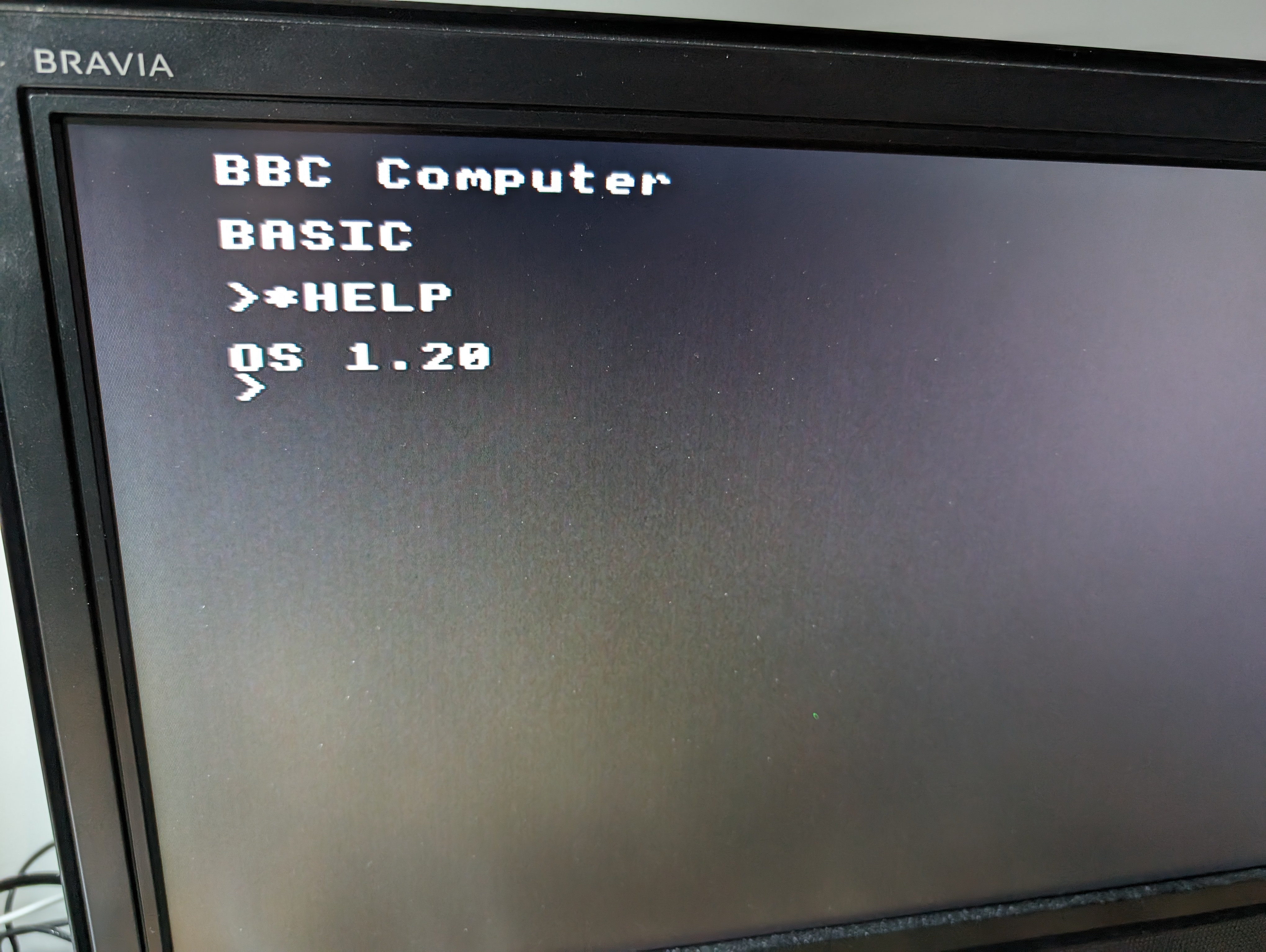
I had to hit “BREAK” for the prompt to show. Otherwise, it would hang after the word “BASIC”. And interestingly, it sometimes claimed to be a 32K machine, and sometimes a 16K machine. This led me to think that IC45 was bad, as that handles the CAS lines between the RAM banks. Unfortunately, it tested fine.
It was also at this point that I found some of the keys on the keyboard were not functioning. So I swapped it out with the keyboard from my other BBC temporarily.
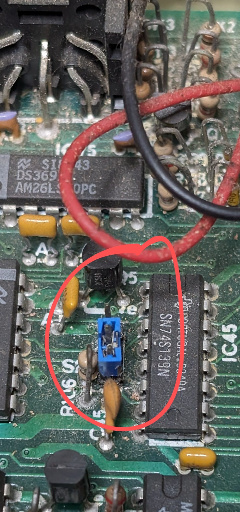
I then found this post. That corruption and behaviour is somewhat similar to what I’m seeing. I pulled IC39, as indicated, and put that in the chip tester.
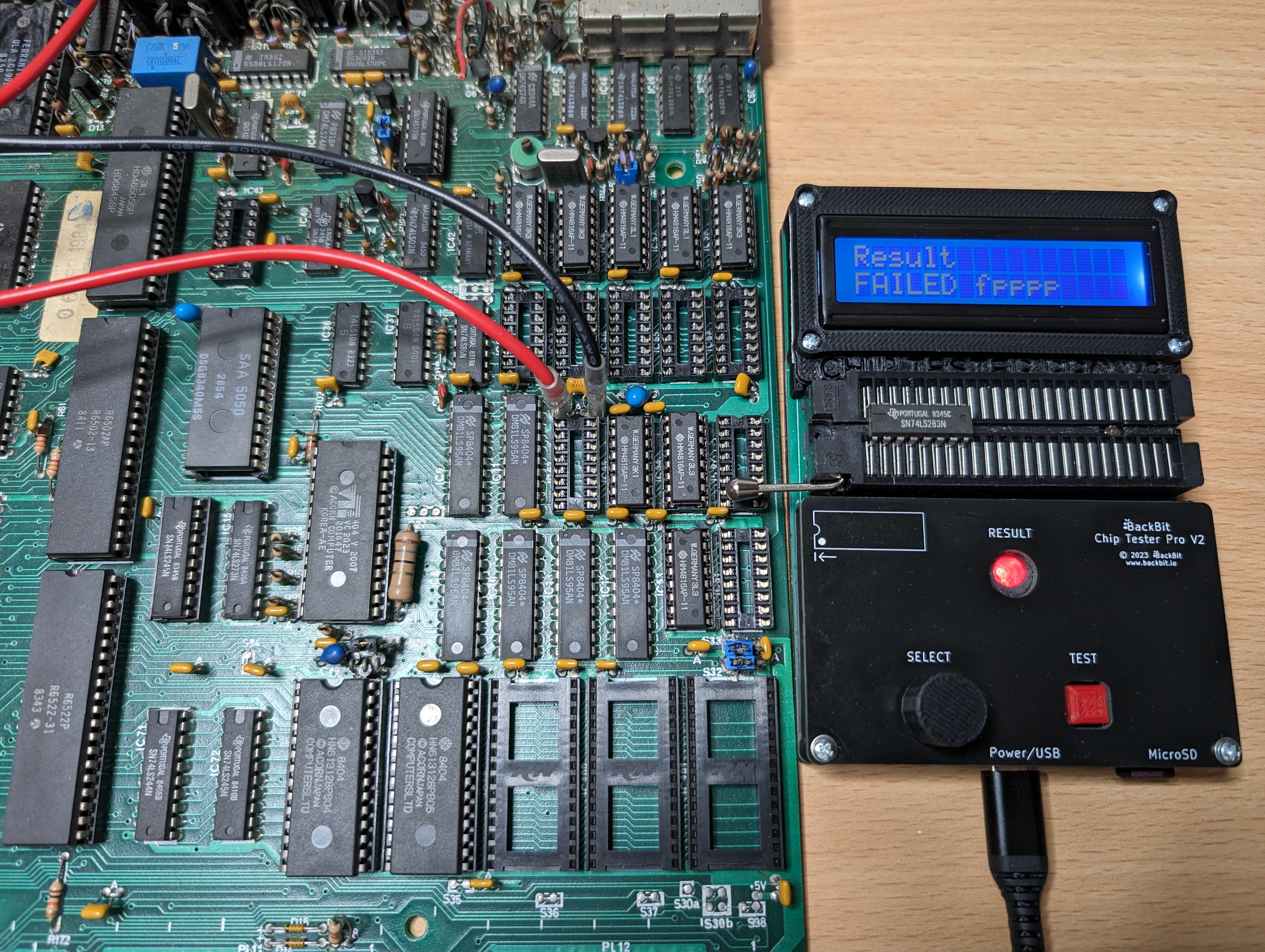
Bingo! That is bad. For confirmation of what specifically is bad, I tested on my T48 programmer.
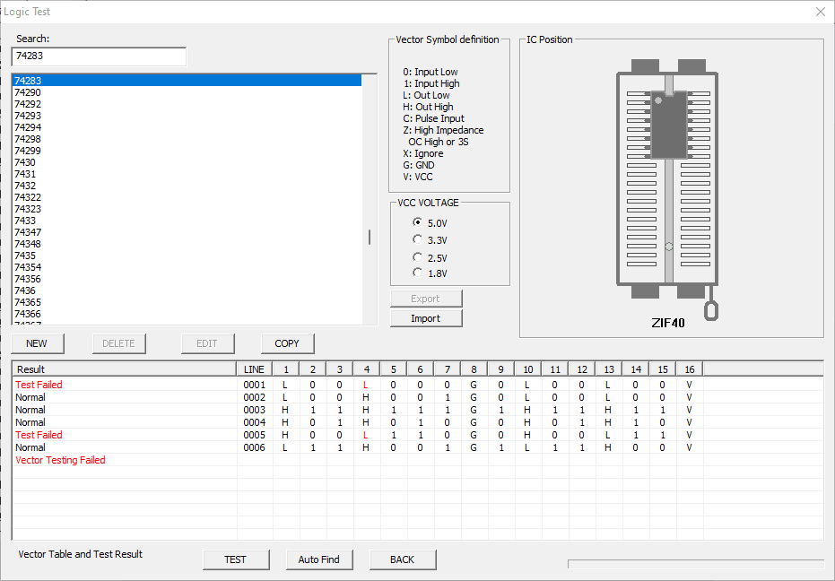
This IC controls the start address for the video RAM. I’m guessing the failure happens to pin it to roughly the correct address for mode 4 to partially work. But will corrupt everything for other video modes.
I popped in a replacement IC and most of the modes worked perfectly again. So I also put new RAM in the low 16K bank and old tested RAM in the upper 16K block so that the chips were matched.
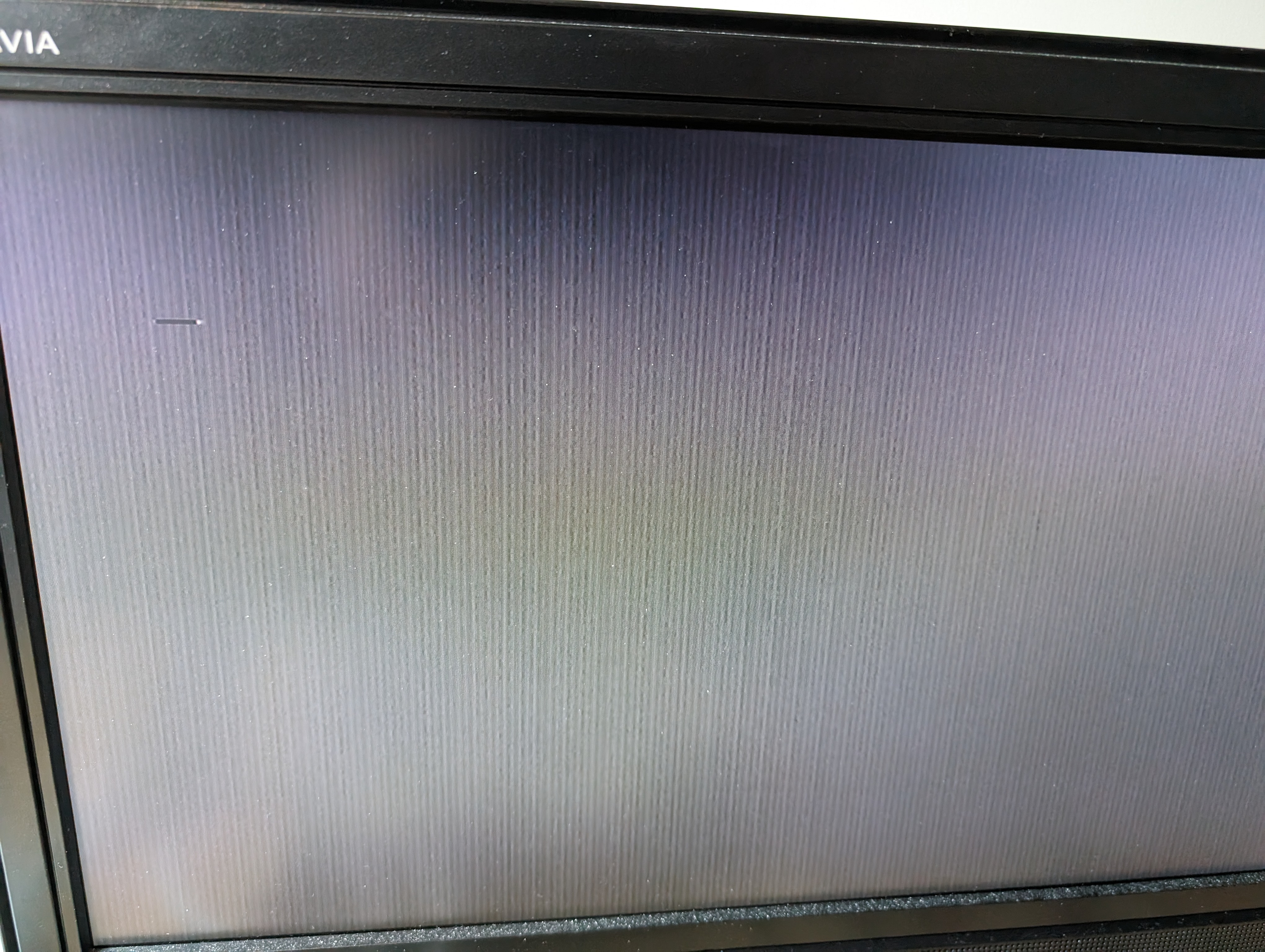
Unfortunately, despite everything else working, mode 7 was still just showing that black cursor from earlier.
Fixing Mode 7
A majority of mode 7 is rendered from the SA5050 Teletext IC, with some of the output coming from the video logic (such as the cursor). Given that it was a black cursor, I wondered if the two were conflicting somehow.
Whilst researching this, I discovered I had done something stupid. One of the first things I did (which I didn’t document earlier in this blog post) was to test all the jumpers to make sure they were making good contact and were in the correct positions. I’ve been stung before by bad jumpers. I noticed that jumper S26 was missing so, I added it in the correct position. S26 decides whether or not to invert the video. Setting it to the west position means normal video, and east inverts it.
It turns out, the missing jumper is intentionally missing. The video ULA chip has several different versions, and version VC2023, which is in this machine, has a bug. The workaround is to remove that jumper and add a patch wire on the bottom, which was done in the factory. Sure enough, mine had a patch wire.

I removed the jumper, set the keyboard so that the machine would boot from mode 7 and…
It appears I did a dumb thing, adding that jumper. But now the machine boots perfectly!
Keyboard
I plugged the original keyboard back in and tried all the keys out. The cursor up and down, copy, delete and return keys were all not working. I flipped the keyboard over and immediately spotted something suspicious.
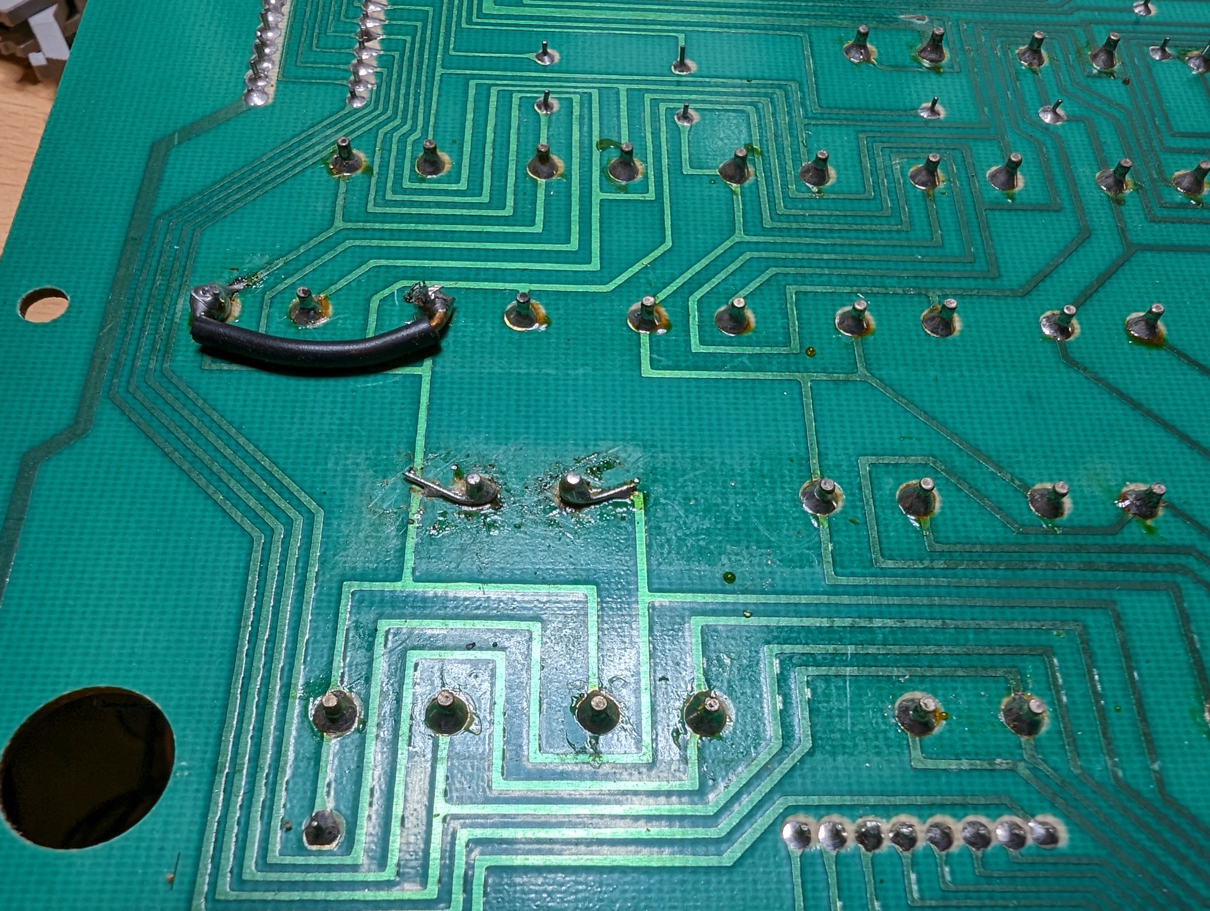
The enter key had two patches, and the cursor keys had a link wire patch. A quick test with a multimeter showed that the left side of the link was not connected to the trace north of it any more. I could redo all of these patches in a cleaner way, but I decided instead to add an additional patch to fix the issue and leave everything as-is for now.
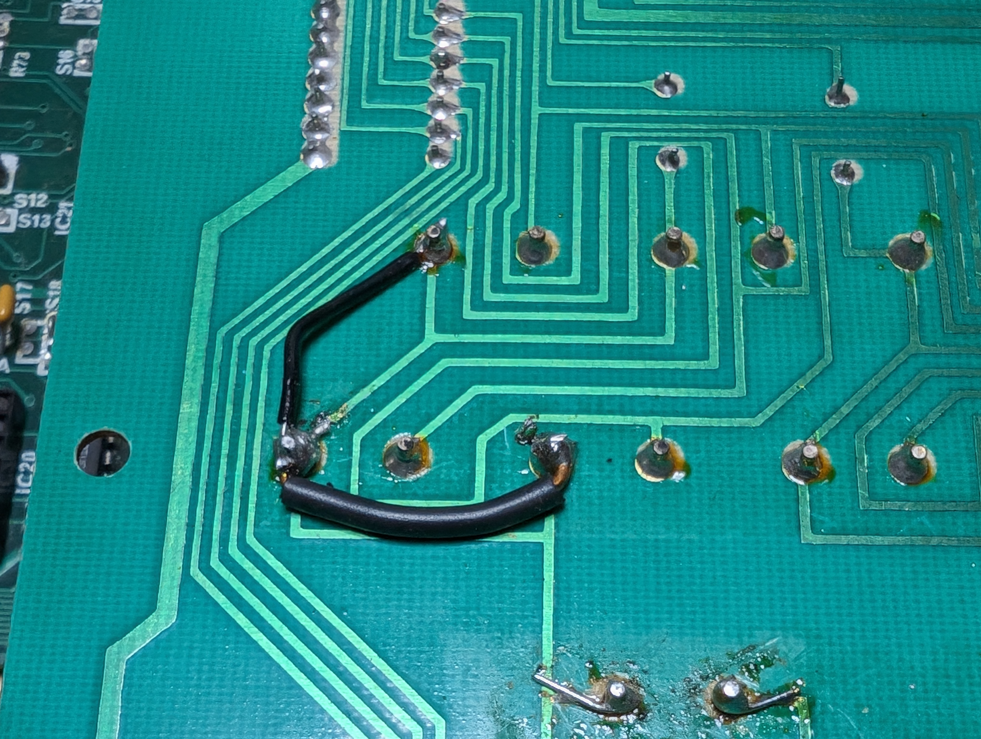
That fixed it! The keyboard is now fully functional, if extremely dirty. But that is a problem for future me.
Summary
This BBC’s motherboard and keyboard are fully functional. So, there are a few things left to do:
- Replace the capacitors in the power supply.
- Clean it.
- Add a replacement missing foot.
- Obtain replacement keyboard screws (one was missing).
- Add a disc interface to it (this one came without one).
- Add any extra ROMs that I want to it.
In addition, I still need to sort the power cable out on the other BBC B.
Still some work ahead, but there is light at the end of the tunnel.
Leave a Reply