I’ve had several customer machines on my bench lately, there is one in particular I think is worthy of a blog post because the repair was weird.
The motherboard
This one is a reproduction Amiga 500 Plus called a Rämixx 500. The layout is like an Amiga 500+, but it has a few minor enhancements.

I added a Terrible Fire 536 with a hard drive for testing.
The basic symptoms were stability issues and graphics corruptions / jitters, particularly on a cold boot.
This is an example:
There is also this example of the corruption and crash screen, which itself had corrupted:


Diagnosis
The first thing I eliminated was the Agnus chip. This chip controls a lot of the video and the RAM, which would make sense for the corruption. But the socket was good, soldered well, and I used one of my stock ones which produced the same results.
The real telltale sign as to where to look is actually in the video above. You can see that not only are graphics the corrupt, but there is a visible glitch on the right side. This is an indication of a video sync issue.
I booted up my oscilloscope to inspect things. The first thing I looked into was the HSYNC, thinking that maybe this wasn’t triggering at the right time sometimes. But I couldn’t spot any issue there.
Clocks
To talk about what I checked next, I first need to explain how the timing works inside an Amiga. The CPU works at roughly 7MHz, but there is a lot more going on than that. I’m going to simplify things a little bit to make this a short summary…
A crystal generates a 28MHz signal (it is slightly more than that and different for PAL and NTSC). This is then fed into a multiplexor because it can also take a 28MHz signal from a genlock device. The output of this is fed into Agnus. Agnus uses this to generate 14MHz clocks that are out of phase with each other, as well as some 7MHz clocks. The 14MHz clocks are used for the video circuit, which made me think that this is what to check next.

Sure enough, the 14MHz clocks glitched on the oscilloscope. So, I speculated that it is the 28MHz input that is the problem.
The WTF moment
Unfortunately, the schematic above doesn’t tell the whole story, so let’s switch to amigapcb.org.

The output of the XTAL goes into FB101 (yellow), this is a 68ohm resistor, the dark blue line is the output of this which goes into the multiplexor. The red line is the output of the multiplexor, this goes into FB102, which is a 150ohm resistor. The output of which to goes a 22pF capacitor labelled E666 connected to ground for EMI suppression, and to Agnus. The other side of the 22pF capacitor is ground.
The signals measured fine until I measured the cyan line. The signal was so small I could hardly read it, around 100mV peak-to-peak. It surprised me that anything was working at all, I had to tweak the oscilloscope quite a bit just to see the signal properly. Agnus is an incredible chip!
Repair
I desoldered E666 and tested it, and this was the “ah ha!” moment. The capacitor measured 220pF, not 22pF. Sure enough, it said 221 on the casing, which is the code for 220pF.

The person who built it accidentally put the wrong value in. The higher value would definitely cause a 28MHz signal to basically flat line.
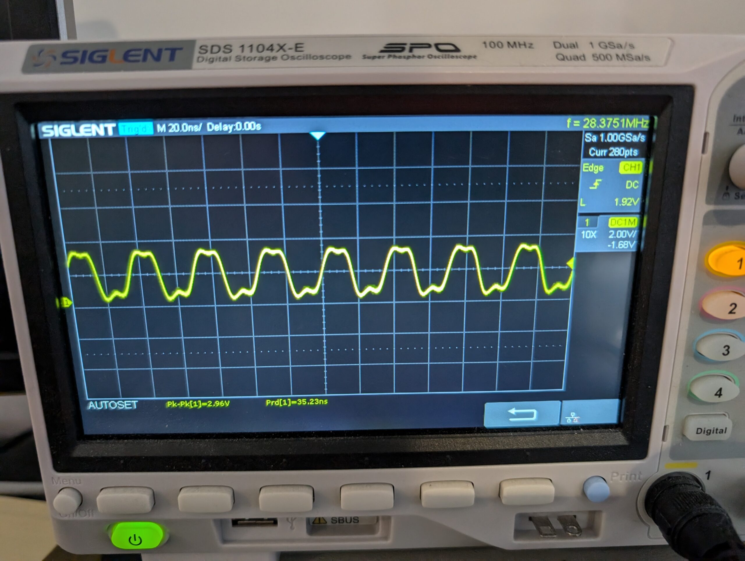
I popped in a 22pF and tested it.


That is much better, a ~3V peak to pear signal. The Amiga was much more stable and the glitches had stopped.
The board is now ready for an ultrasonic clean and sending back to the customer.


Leave a Reply