
In my previous post I had everything running to a satisfactory level, but I was still running from a bench power supply. Time to sort that out…
Building the PSU
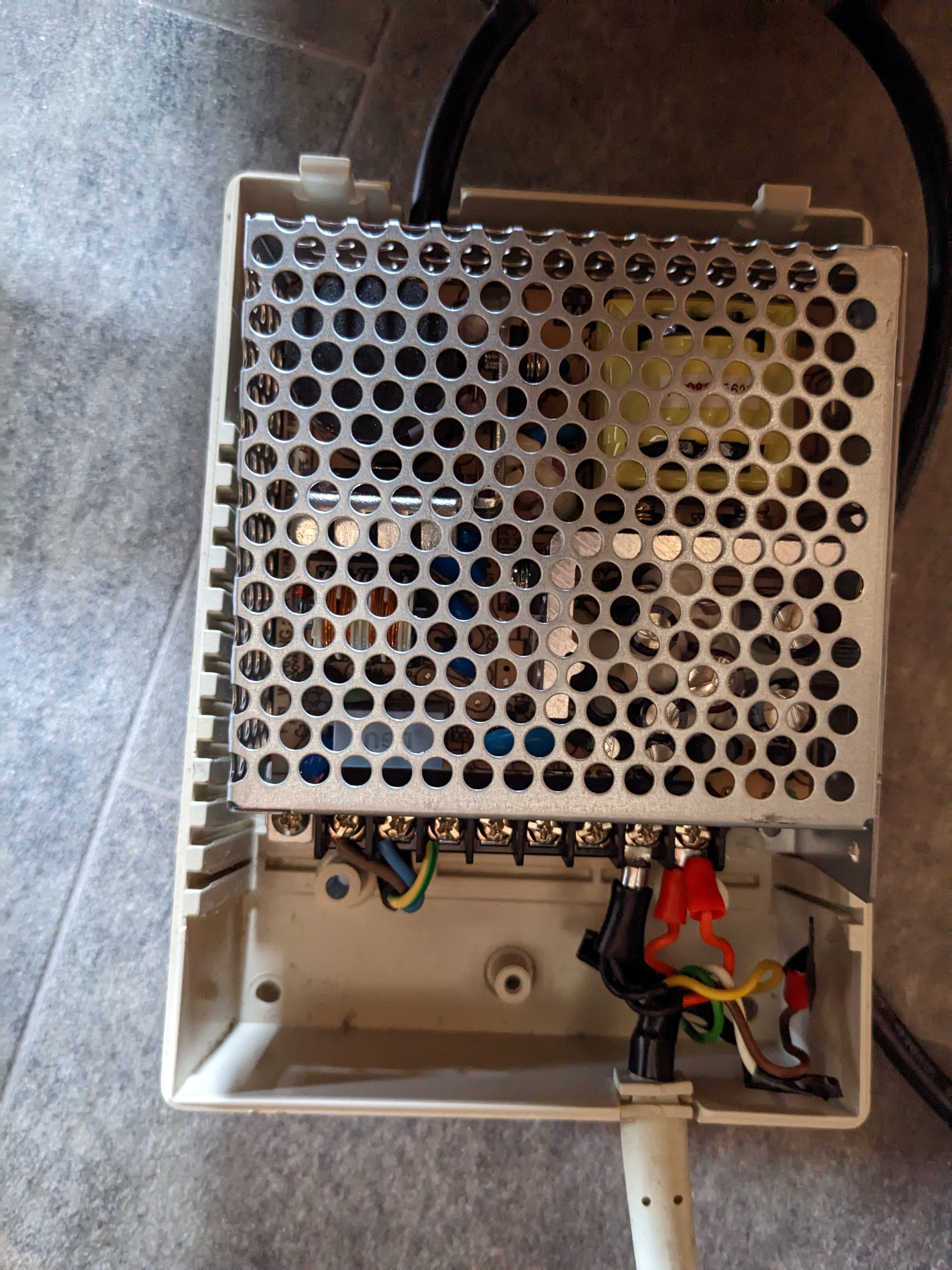
When unpacking the PSU I noticed that the 3-pin plug was not that healthy.

I’m guessing wherever it was stored was a little damp and the copper in the pins suffered accordingly. As for the PSU itself, it is a mix of a SWPS for the 5V rail and linear regulators for the +12v and -12v. It also has a wire to turn the PSU on when grounded, very much like an ATX PSU. This is wired to a latching switch at the back of the Euro PC.

I’m not an expert at restoring power supplies and I didn’t really trust this one. So, I decided to replace the internals with a Meanwell RT-50B. I have those units lying around my workshop because I use them for Amiga restorations. The voltages required by the EuroPC are the same and it is well within spec for the current requirements. I had to cut away a bit of plastic on the PSU case to make this work but I’m not really upset about that, I just wish I could have implemented some strain relief on the mains cable.
On my bench power supply I was just running the +5v and GND. The +12v and -12v are only used for the ISA card connector, so I didn’t need them when testing. I did originally wire them into this quick hacky job I made below, you’ll notice they aren’t wired in right now and I’ll get to that. It does mean the power switch on the EuroPC is useless for now, but I can live with that.
Disaster
After many tests to make sure I had the wiring correct and there were no shorts I powered the machine up, it was working fine but in a few seconds I heard a fizzing noise coming from the EuroPC. I immediately cut the power to investigate.
There was a unique odour coming from the motherboard. As the only thing I changed was the addition of the +12v and -12v I checked those. Suddenly I found a short between +12v and GND that was not there before. Uh oh!
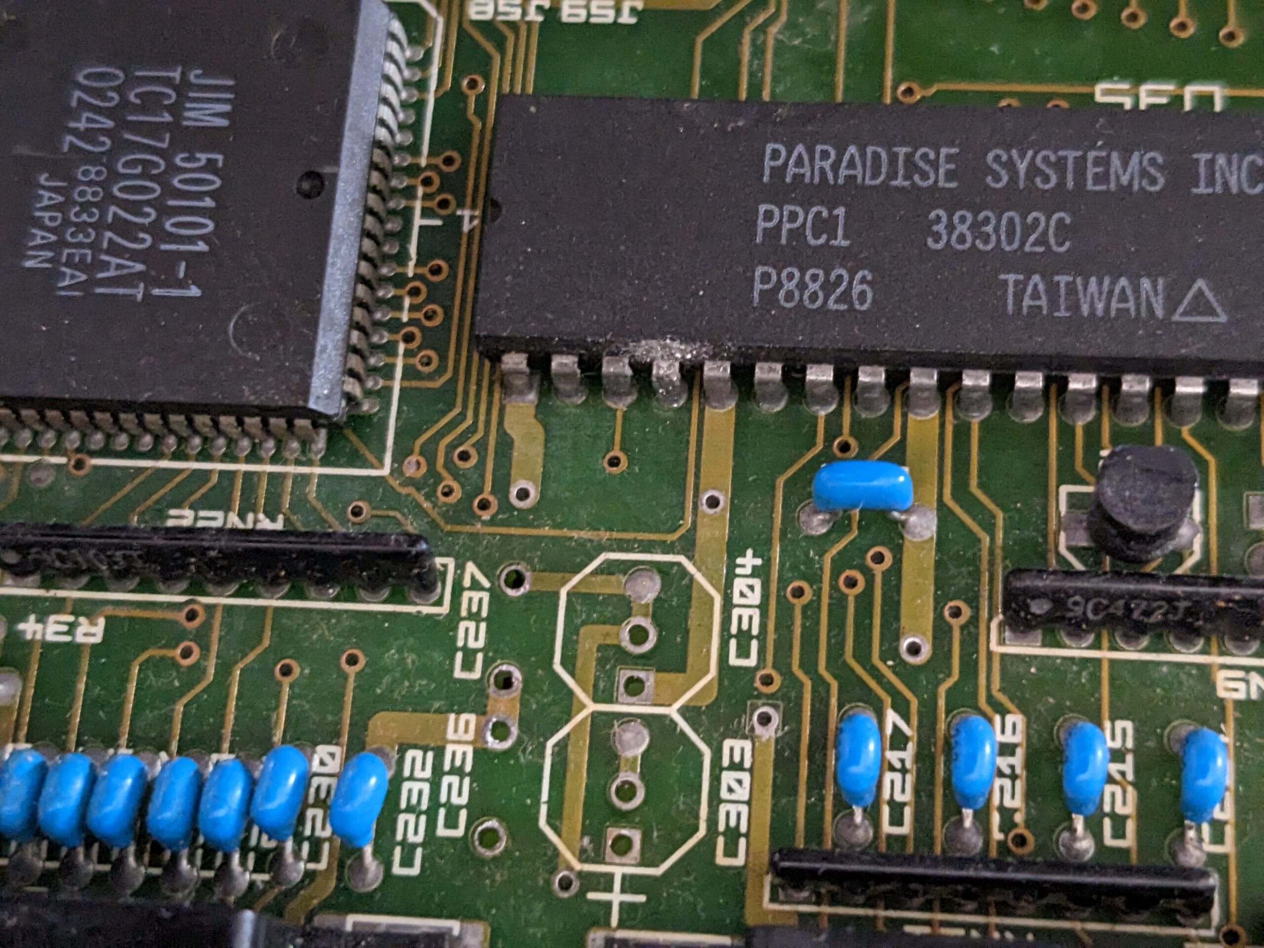
Time to look at the schematics. There are some 10uF capacitors there which I don’t remember seeing, unless, oh no…
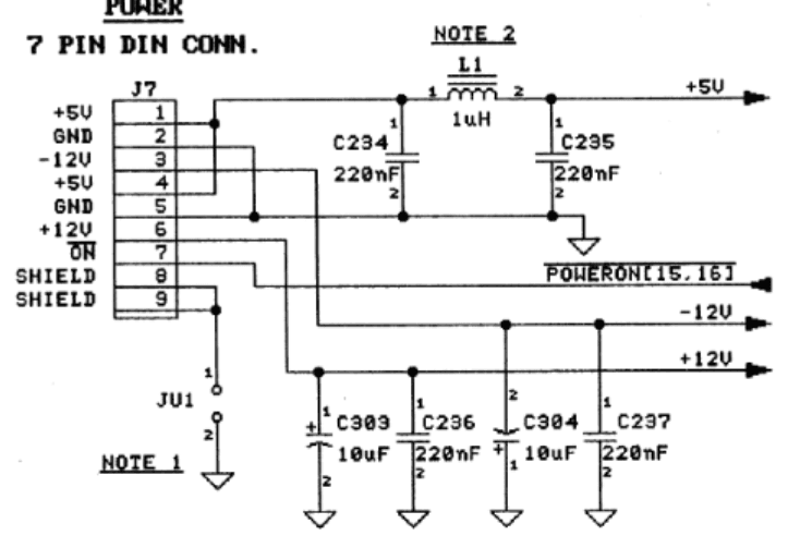
It turns out they are tantalum capacitors. Why is that a problem? Because when they fail, they fail short circuit. This capacitor had shorted between +12v and ground. This could be very bad. The Peak meter didn’t know what to make of it. But on a multimeter it is pretty much a 0ohm resistor now.

Looking at the motherboard, it appears the parallel port chip might have taken damage, although it could be exhaust from the capacitor, I couldn’t see any obvious signs of it coming from the capacitor though. I have no way of testing the parallel port yet, but I’ll buy something to plug into there to test it. The PSU has short circuit protection inside it so it hopefully cut things very quickly.

I fired up the machine again with just 5v and everything else seems to be working fine. That chip is not getting hot on the thermals (it didn’t before). I guess we will see in future tests. For now I’m going to replace these capacitors with equivalent electrolytics, and I probably won’t hook up the 12v lines back up for now anyway because it is unlikely I’ll ever need them.
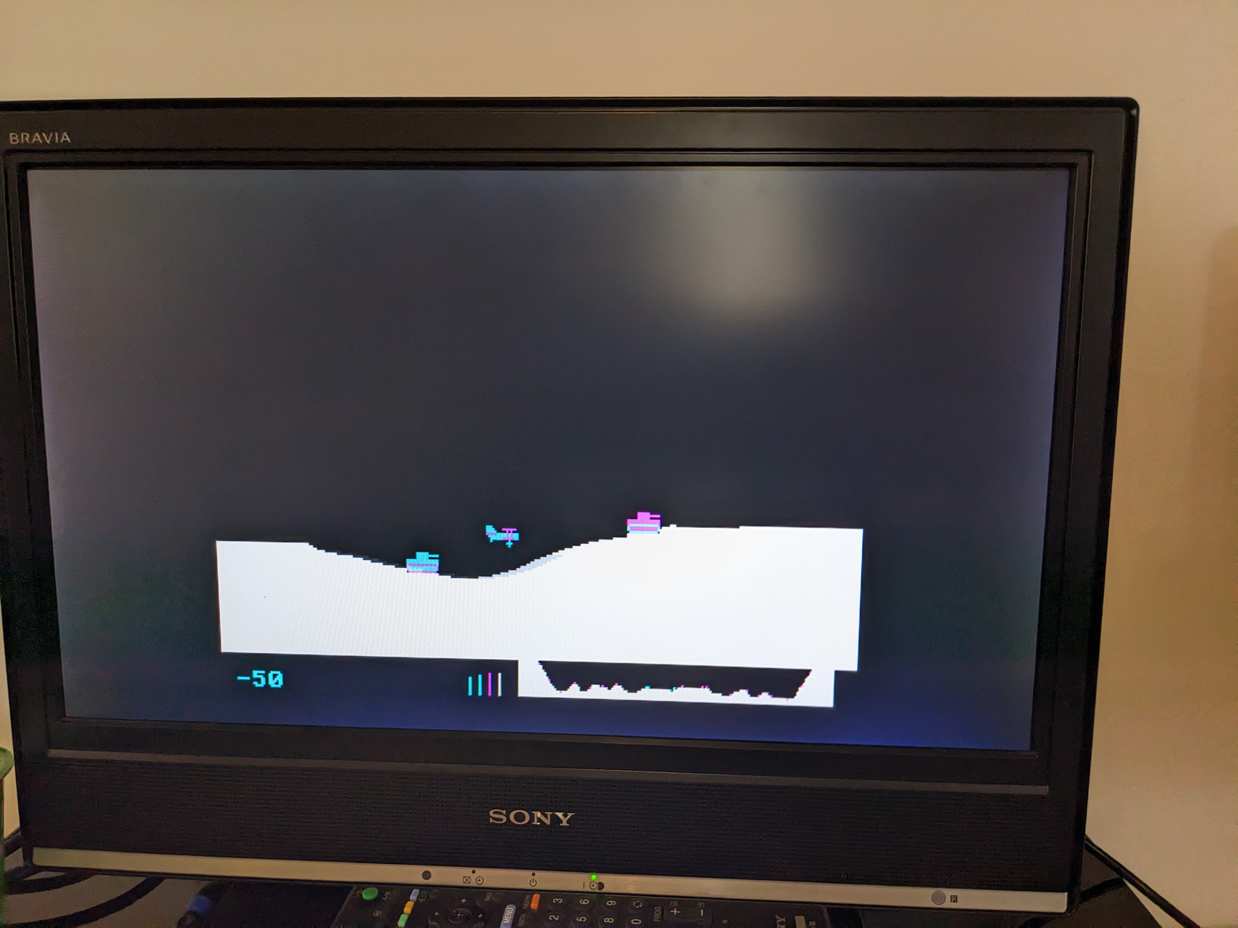
Here is a game running on it called Sopwith which I have never played before and have not figured out the controls. But it works great even after the “incident”.
Leave a Reply