

In recent years, Microchip has launched a new range of AVR chips. They appear to have had some things borrowed from the PIC range, and you have to do some things a little differently. That being said, they are very powerful, feature rich and relatively inexpensive. I started using them earlier this year. I thought I would share what I have learnt.
About the family
I believe the chips were launched 4 years ago, and are now very easy to obtain. Their model numbers work like this AVRxxyyzz, where:
- xx – The number of kilobytes of flash, 16 – 128.
- yy – The range in the family, currently DA, DB, DD or EA
- zz – The number of pins on the chip
I won’t dig into all the features of each range here. But there were a couple of things that attracted me. The first is a built-in accurate crystal oscillator, capable of running the chip at 24Mhz at 5v, which is quite fast for an 8bit microcontroller. In addition, at the time of writing, they are very cheap for everything you get. I have been able to obtain the AVR32DA48 QFN chips I have been using at a little over £1 + VAT. I also used AVR64DA64 QFP chips, and they are still less than £2 each.
Software differences
I don’t use the Arduino IDE, libraries or anything like that. I prefer using avr-libc directly and use my own Makefiles and editor. There are a few things that are different here. Microchip has a pretty decent migration guide available, unfortunately I didn’t see this until I was deep in the weeds and had figured a lot of things out. I recommend most people going down this path jump straight to section 2.4 where you will see this table:
| megaAVR® | AVR® Dx | Description |
|---|---|---|
| DDRx | PORTx.DIR | Data direction – controls the data direction (output driver) |
| PORTx | PORTx.OUT | Data out – controls the output driver level for each PORTx pin |
| PINx | PORTx.IN | Data in – shows the state of the PORTx pin |
There are additional utility members of those structs that allow you to set and clear individual bits of the port output and direction easily. I won’t dig into it all here, but this chapter is probably the most important starting point.
Programming
I suspect many people are using to flashing using SPI, or maybe something like HVSP for the smaller chips in the range. Throw all that knowledge out of the window. The AVR Dx range uses something called UPDI (Unified Program and Debug Interface).
UPDI is a single-pin serial programming and debugging interface for the chip. The advantage of this is, of course, more pins are available to the user. The disadvantage is that it is relatively new and, from what I read, it has been a pain to reverse-engineer for people writing open source tools. I believe most things are now implemented.
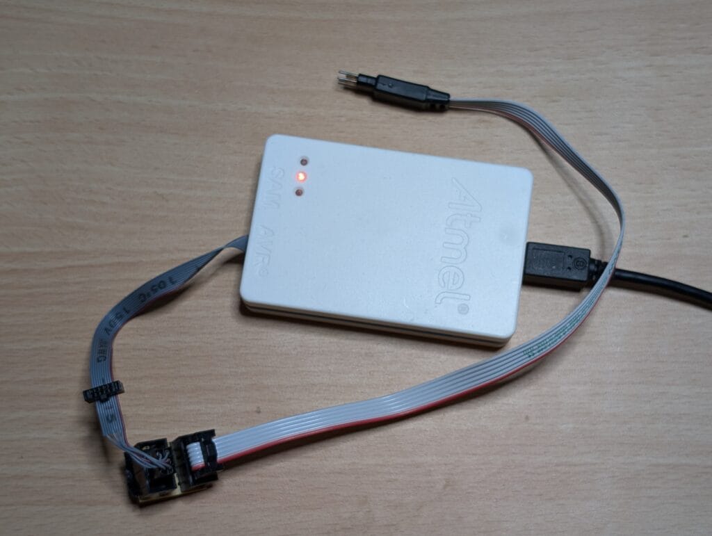
I happen to have an Atmel-ICE programming device, which made it quite easy to program. PICkit 4 devices can also program them. If you don’t, there are ways of using an FTDI serial-based programmer with a resistor to connect Rx and Tx together. I have not tried this myself, so have not detailed it here. But you should be able to find details easily online.
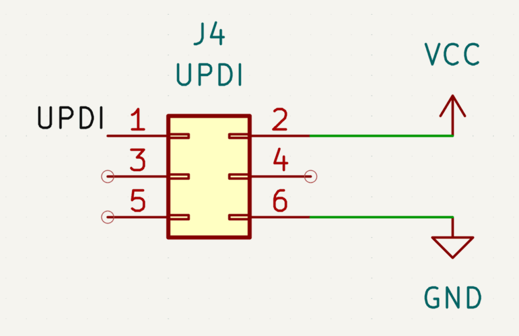
If, like me, you want to use an official method, this is the standard pinout for 6-pin UPDI:
I typically use TagConnect connectors when programming. This gives me a nice small footprint that I can just push the sprung connector onto without soldering. I therefore cobbled together a male to male converter because both TagConnect and Atmel-ICE have female connectors. But this bit of stripboard is just a 1-to-1 pin mapping underneath.
Makefile
With all that being said, this is the base Makefile I’m using to build and flash chips. Note that you will need a relatively recent avr-gcc / avr-libc and avrdude. At the time of writing, I’m using Fedora 40, and I had to update avr-libc to the version in the Fedora 41 alpha packages and avrdude from source to make this work.
With that being said, here is my Makefile:
# The MCU model
MCU=avr32da48

# Clock speed used (after divider), mostly for delay functions
CLK=4000000
# Name of project output file
PROJ=my_project
# List of source files
SOURCES=main.c more_code.c

# List of object files generated from source files
OBJ=$(SOURCES:.c=.o)

all: $(PROJ).hex

# Generated object files
.c.o:
        @echo "Compiling $<"
        @avr-gcc -w -Os -flto -Wall -Wextra -DF_CPU=$(CLK) -mmcu=$(MCU) -c -o $@ $<

# Generate executable
$(PROJ).elf: $(OBJ)
        @echo "Linking..."
        @avr-gcc -w -Os -flto -mmcu=$(MCU) $(OBJ) -o $(PROJ).elf
# Create Intel hex format for programming
$(PROJ).hex: $(PROJ).elf
        @avr-objcopy -O ihex -R .eeprom $(PROJ).elf $(PROJ).hex

size: $(PROJ).elf
        @avr-objdump -Pmem-usage $(PROJ).elf

clean:
        @rm -f *.hex *.elf *.o

# Install flashes the code
install:
        avrdude -c atmelice_updi -p $(MCU) -e -U flash:w:$(PROJ).hex -U lock:w:0xA33A3AA3:m
This can look a bit daunting, but I will go through it now. I should note that if you are copy/pasting, the indentation needs to be tabs.
First we have the MCU, this is simply the model you are using. The package of the chip doesn’t really matter. Then the CLK, the default for the AVR-DA range is to use the internal crystal oscillator and divides it down to 4MHz. This needs to be set so that things like delay functions can be used, you could also do this in your code instead.
The PROJ name basically gives the output files a name and SOURCES is a list of your .c files.
When running make, the .c.o section is executed first, this creates compiled object files for each .c file. Then all the objects are linked together to create the final binary. This in-turn is converted into a .hex file so that it can be flashed.
There are a few extras here as well make clean does the obvious, clean up the build artefacts. Then there are a couple of extras to focus on. The first is make size, this shows how much flash and RAM will be used by your project. When you use this, you will see an output like this:
my_project.elf:     file format elf32-avr
AVR Memory Usage
----------------
Device: avr32da48

Program:    3035 bytes (9.3% Full)
(.text + .data + .rodata + .bootloader)

Data:        396 bytes (9.7% Full)
(.data + .bss + .noinit)
Then there is make install. This I need to dive a little more into, as you may need to change it. This is line will erase the chip, flash it with firmware and then lock the chip. It is work noting at this stage that fuses and locks that you are used to are completely thrown out of the window.
Fuses are now named (see the datasheet for your chip) and locks are now 32bit. The theory I see behind this is that it makes it harder to manipulate into flipping than a single-bit lock. The value of 0xA33A3AA3 is the recommended setting because it is the inverse of the default unlocked setting of 0x5CC5C55C, but any other value will work here. Once the device is locked, you can’t even write to it, the only action you can do is erase.
Now, for the bit you will likely need to change. The cable. I’m using an Atmel-ICE to program my boards. Not everyone will have that. So you can replace atmelice_updi with one of the following:
  atmelice_updi      = Atmel-ICE (ARM/AVR) in UPDI mode
  jtag2updi          = JTAGv2 to UPDI bridge
  nanoevery          = JTAGv2 to UPDI bridge
  jtag3updi          = Atmel AVR JTAGICE3 in UPDI mode
  pickit4_updi       = MPLAB(R) PICkit 4 in UPDI mode
  pkobn_updi         = Curiosity nano (nEDBG) in UPDI mode
  powerdebugger_updi = Atmel PowerDebugger (ARM/AVR) in UPDI mode
  serialupdi         = SerialUPDI
  snap_updi          = MPLAB(R) SNAP in UPDI mode
  xplainedmini_updi  = Atmel AVR XplainedMini in UPDI mode
  xplainedpro_updi   = Atmel AVR XplainedPro in UPDI mode
There are a lot of options available, some you can pick up relatively cheaply or build yourself. If you search around the internet, there will be lots of information available.
Final thoughts
Hopefully, this is a good enough intro to help people like me, who were not expecting these chips to be so different. I highly recommend reading the Microchip PDF I linked to in this document to learn more about the differences.
Leave a Reply