
A lot of people use Meanwell power supplies as the replacements for the poor quality ones that came with the Amiga. Typically, the 50W variants such as the RPT-60B are used because it fits nicely inside an original Amiga power supply. I wanted to see if I could use a 75W PSU for heavily upgraded Amigas. Here is the journey.
The PSU
For those who don’t know, Mean Well power supplies are relatively inexpensive, but are very high-quality power supplies. You can normally decode their model numbers using the following rules:
- First letter or two letters is the type, “R” is an enclosed cased PSU that is also used in Amigas, “RP” is an open-frame design and medical grade.
- The last letter in the first group is the number of outputs, “S” for single, “D” for double and “T” for triple.
- The number is roughly akin to wattage, although the RPT-60B is only 50W in the datasheet.
- The final letter designates the voltages on the outputs. “B” gives you 5V as the primary voltage, with +12V and -12V as additional outputs. Idea for an Amiga.
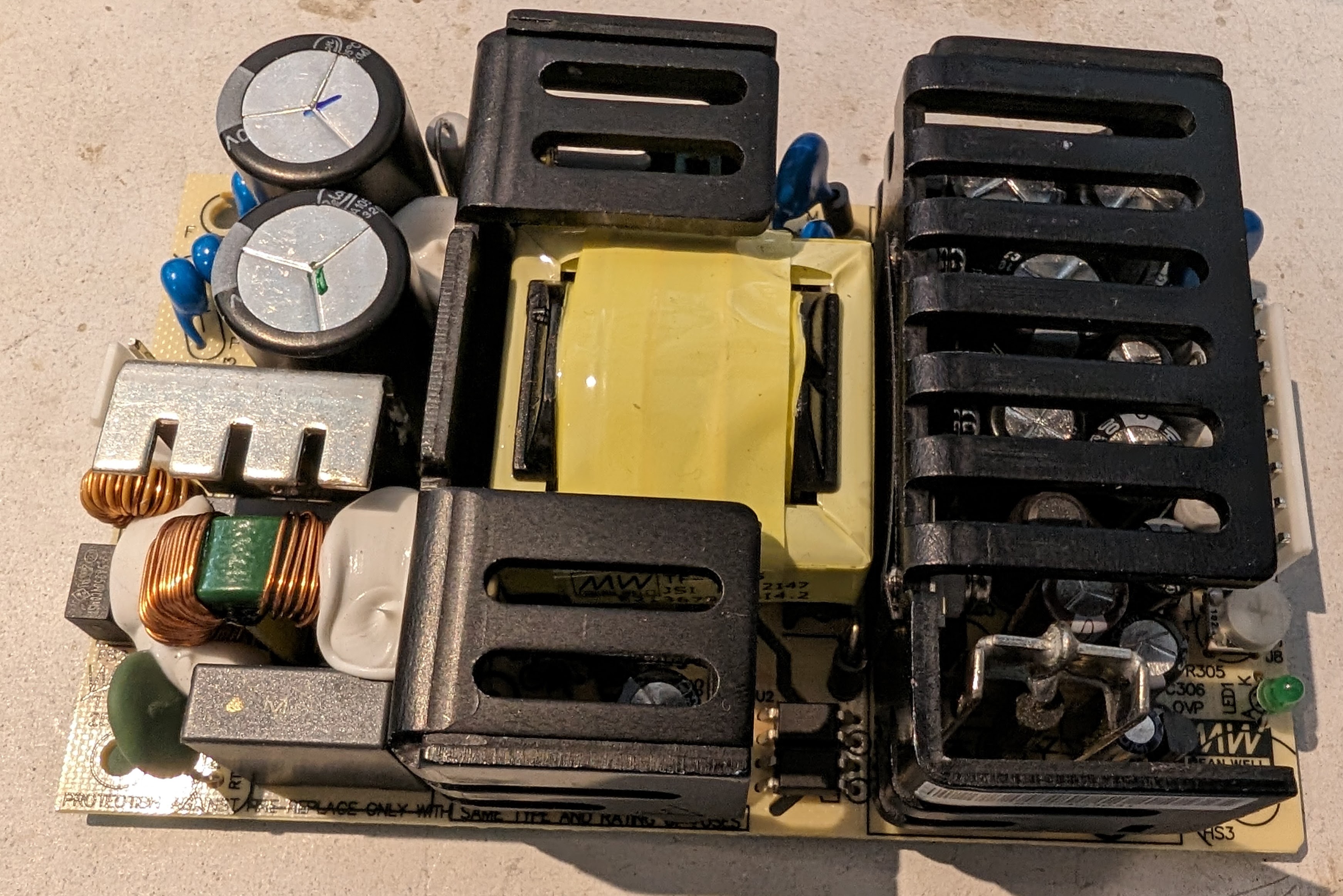
The RPT-75B is a medical grade open-frame power supply rated at 72W. It provides 6A on the 5V rail, which should be plenty for PiStorm32-Lite with a Raspberry Pi 4 and other upgrades.
My hope was that this power supply would fit in a regular Amiga power supply case, unfortunately it is ever so slightly too long. So, I decided to design a new one.
Wiring
I should preface this with a disclaimer: do not try this at home if you are not used to dealing with mains voltage electronics. If you are unsure, get a qualified electrician to help.
Retro32 created a nice guide to using the RPT-60B, and a lot of the wiring steps can be followed there. One key thing to note is the section at the end of the power supply datasheet.
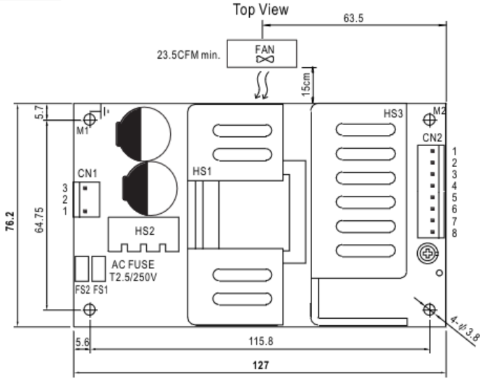
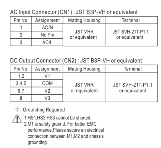
So, the AC in is pretty obvious. The outputs in this case are 5V for V1, +12V for V2 and -12V for V3. But also pay attention to the grounding requirements. M1 and M2 have pads underneath them which should be linked to ground. This is actually somewhat helpful because you have (in the UK) ground coming in from the mains power cable and that is usually connected to the shield wire on the Amiga connector. So, you can wire the mains in ground to M1, the Amiga ground to M2 and create a link wire between them.
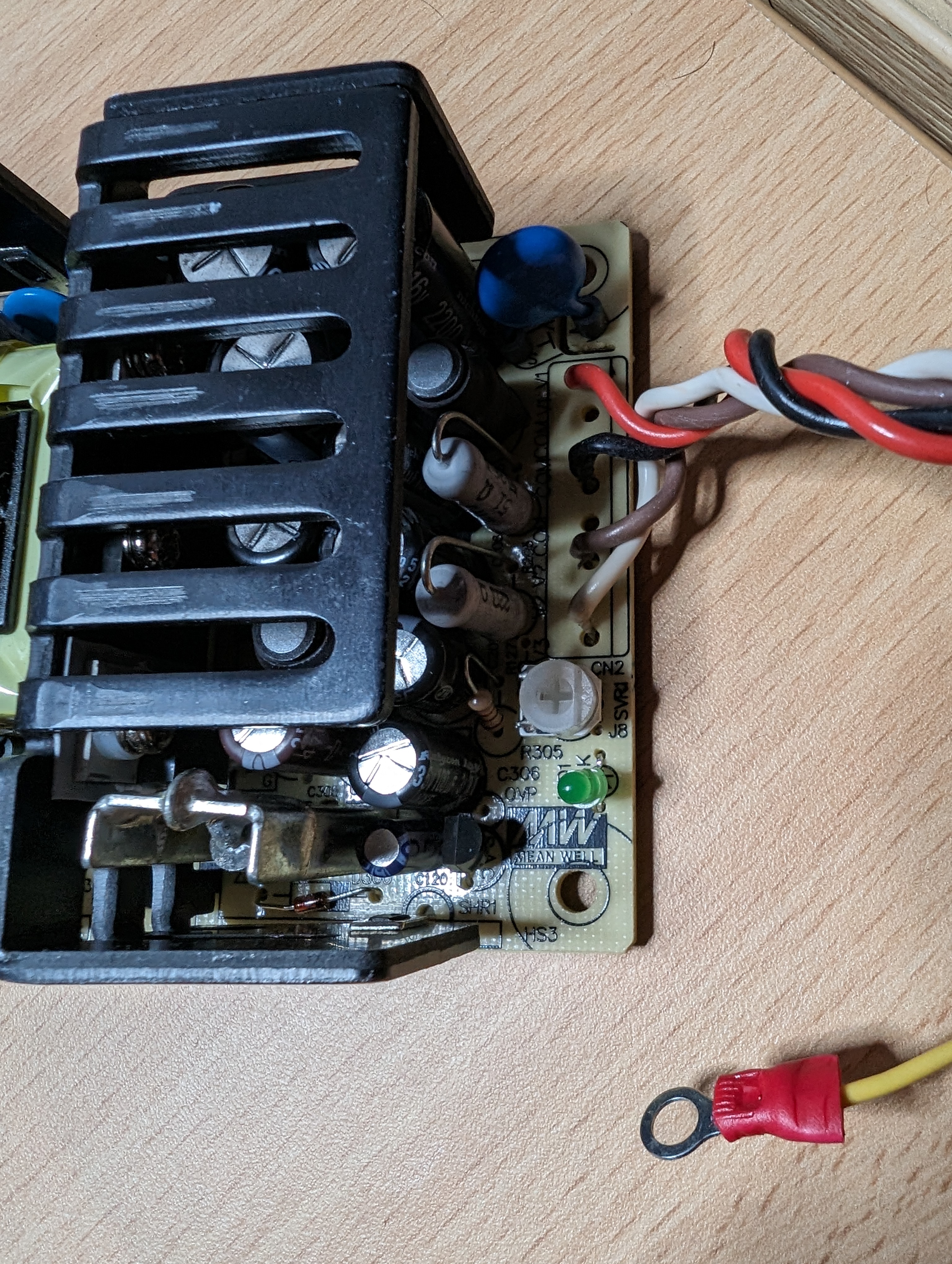
I could have crimed connectors onto the wires connecting to the PSU, but I instead decided to solder directly to the board. This, of course, meant desoldering the old connector, which the Hakko FR-410 with a slightly larger than normal nozzle handled without issue.
On the low voltage side, I wired the cable as below (see the Retro32 post I linked to above for more information there). The earth ring is crimed and soldered on.
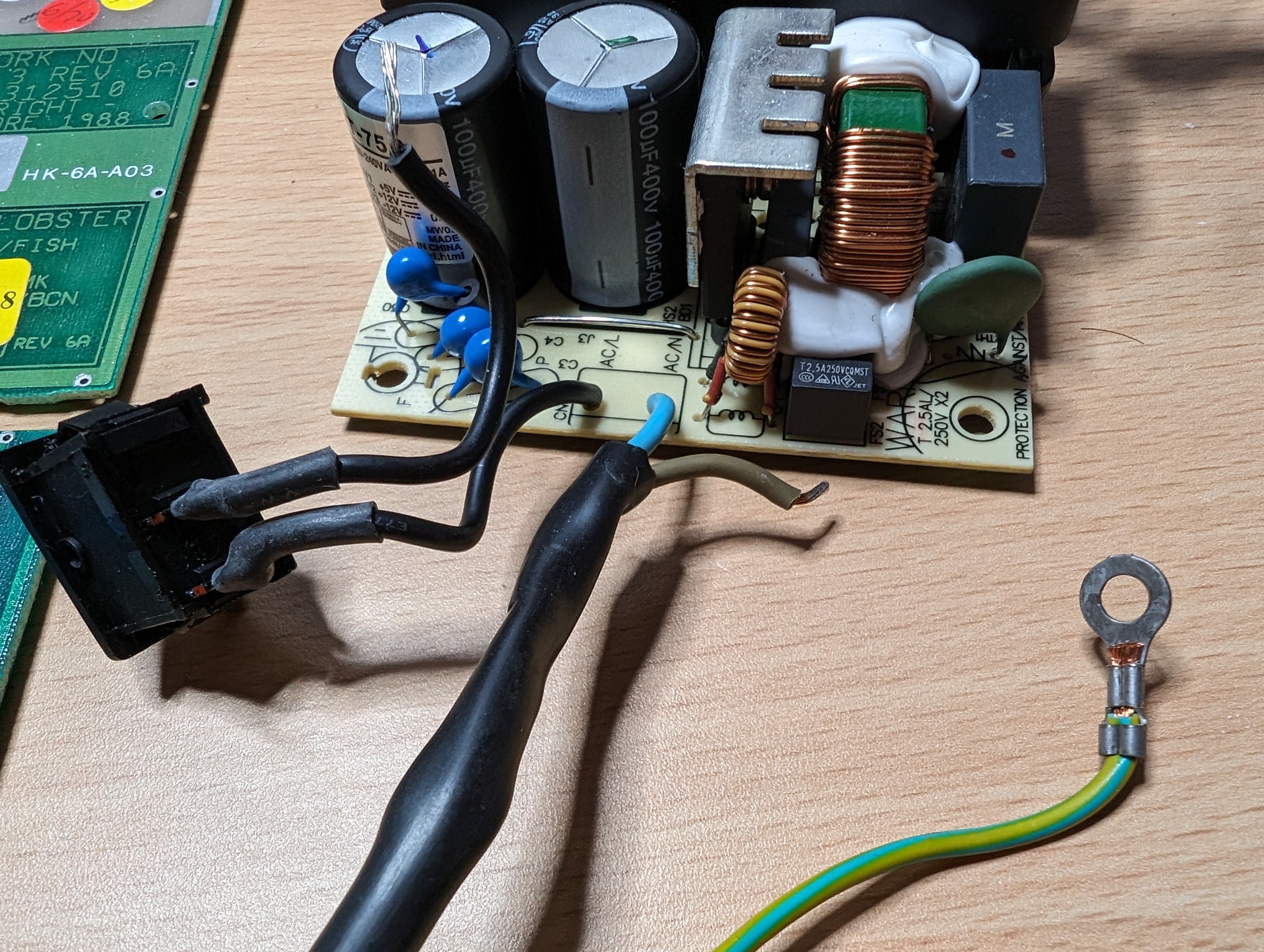
For the high voltage side, I wired the Neutral directly to the board, as well as one of the switch wires. I intend to use a Wago connector to link the Live wire to the other switch wire.
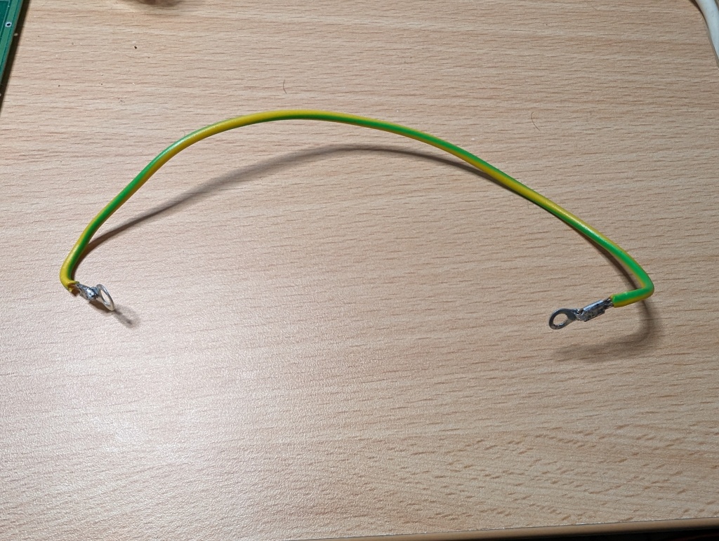
I also created an earth link wire to bridge the two earthing points. Again, crimping and soldering the rings.
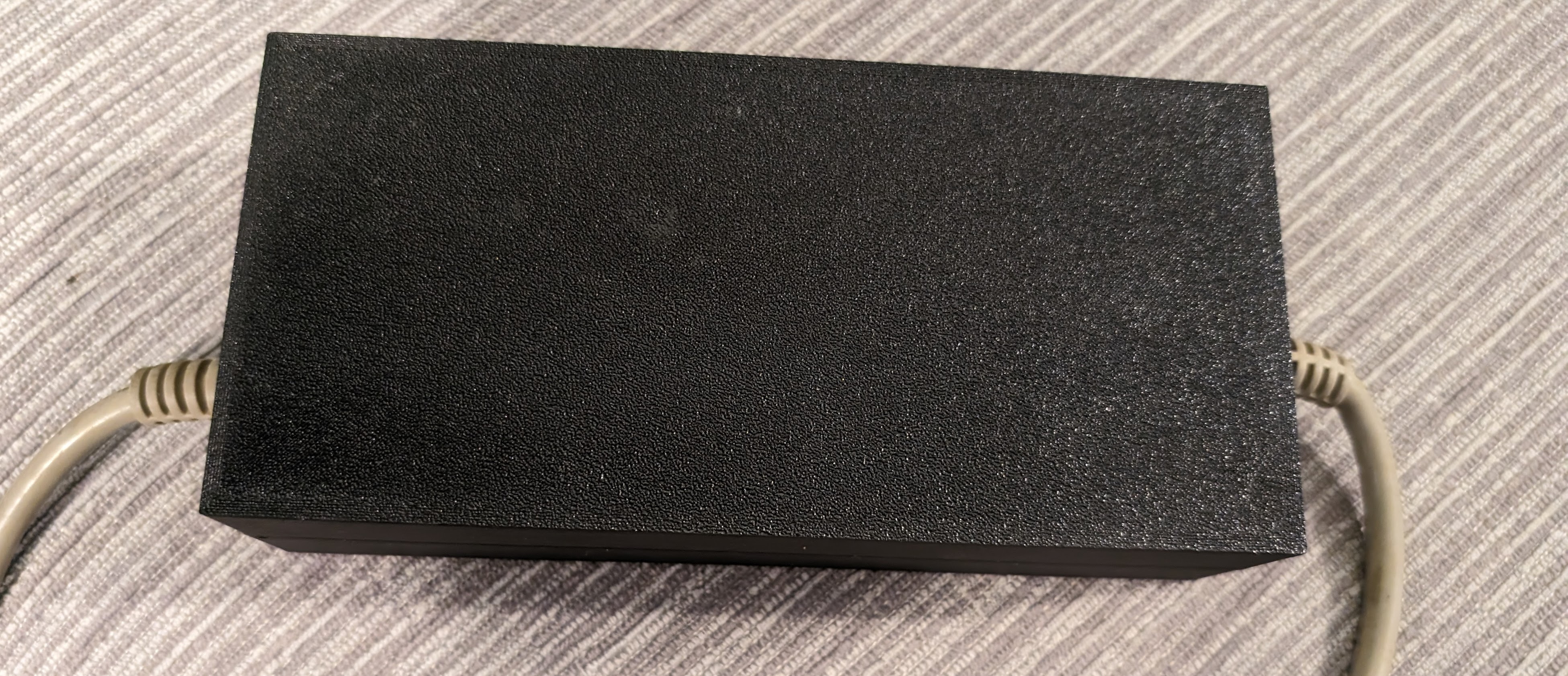
Casing
This took a few tries to get right, I first intended to have it so that M3 screws were used to secure the board, but this failed for two reasons:
- it was very difficult to get the earth rings to line up with the holes on both sides when screwing it down.
- The mounts weren’t quite strong enough.
So, I ended up with a design that uses M3 bolts and nuts to secure the board and M4 screws to hold the case together (although it press-fits quite tightly as well).
I have made this design available on Cults.
When fitting, I used 16mm M3 bolts, which allowed me to hook the earth links on before placing the board on top.
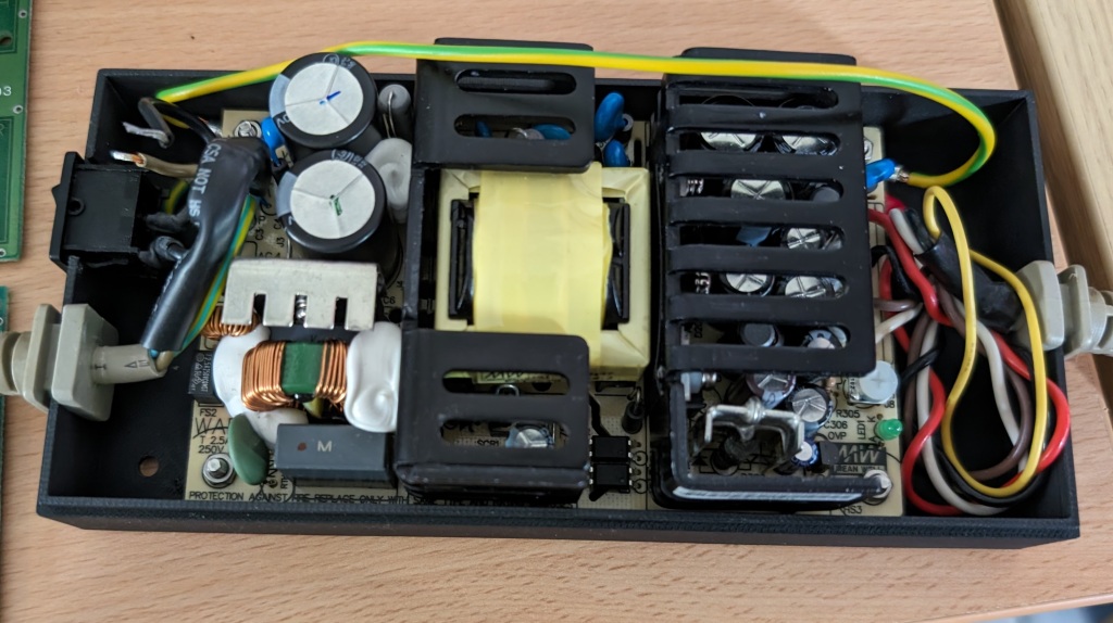
I haven’t connected the Live with the Wago at this stage, but you can see the PSU board bolted in. At this point, everything was checked to make sure continuity was as it should be, particularly with grounding.
When a new batch of two-terminal Wagos finally turned up, I fitted one.

Again, continuity was double-checked to make sure all was good.
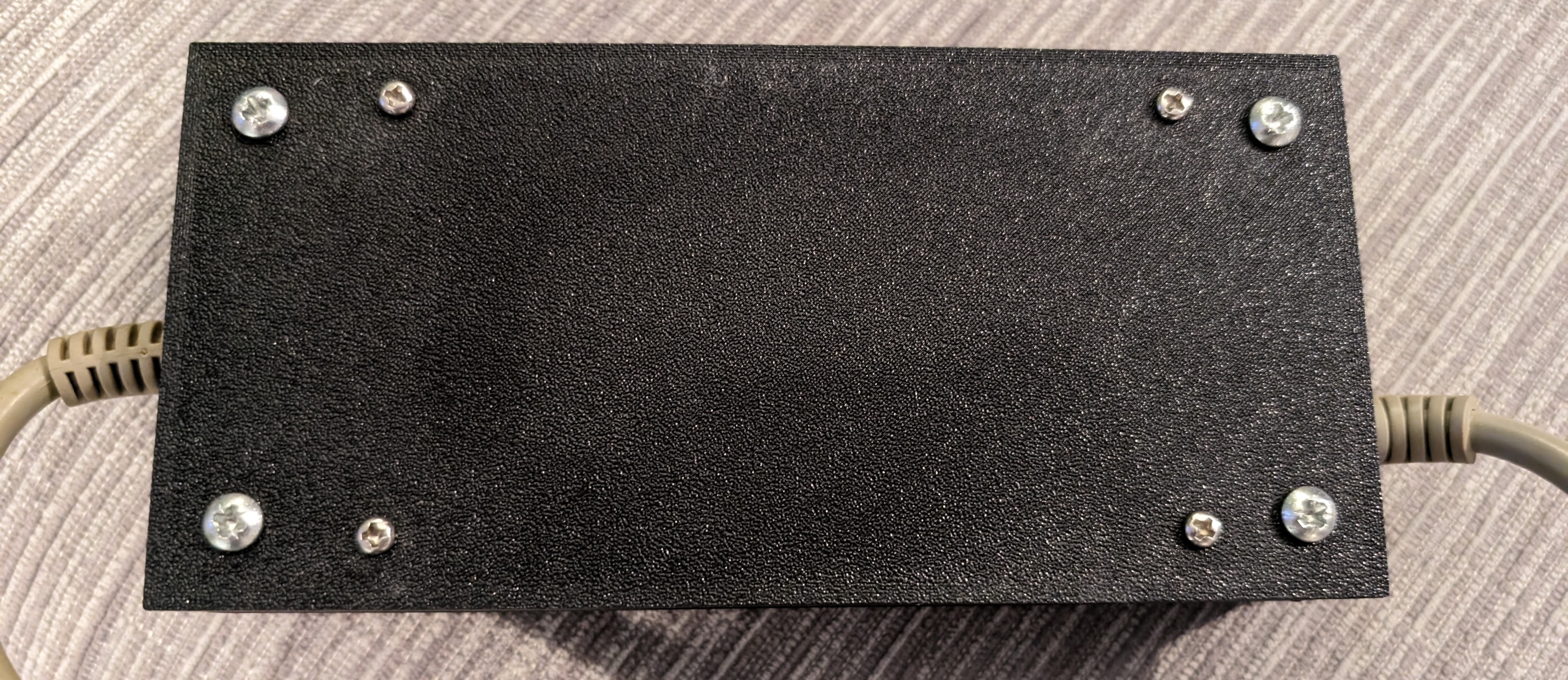
The two halves of the shell were screwed together using M4 38mm screws. Much shorter screws would have been fine, but I can definitely be assured it is secure.
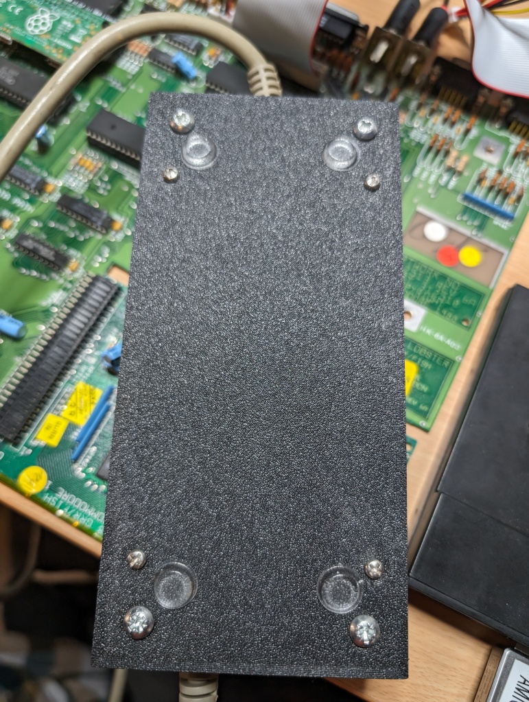
For the final touch, I added 3M rubber bumpons to act as the feet.
Testing
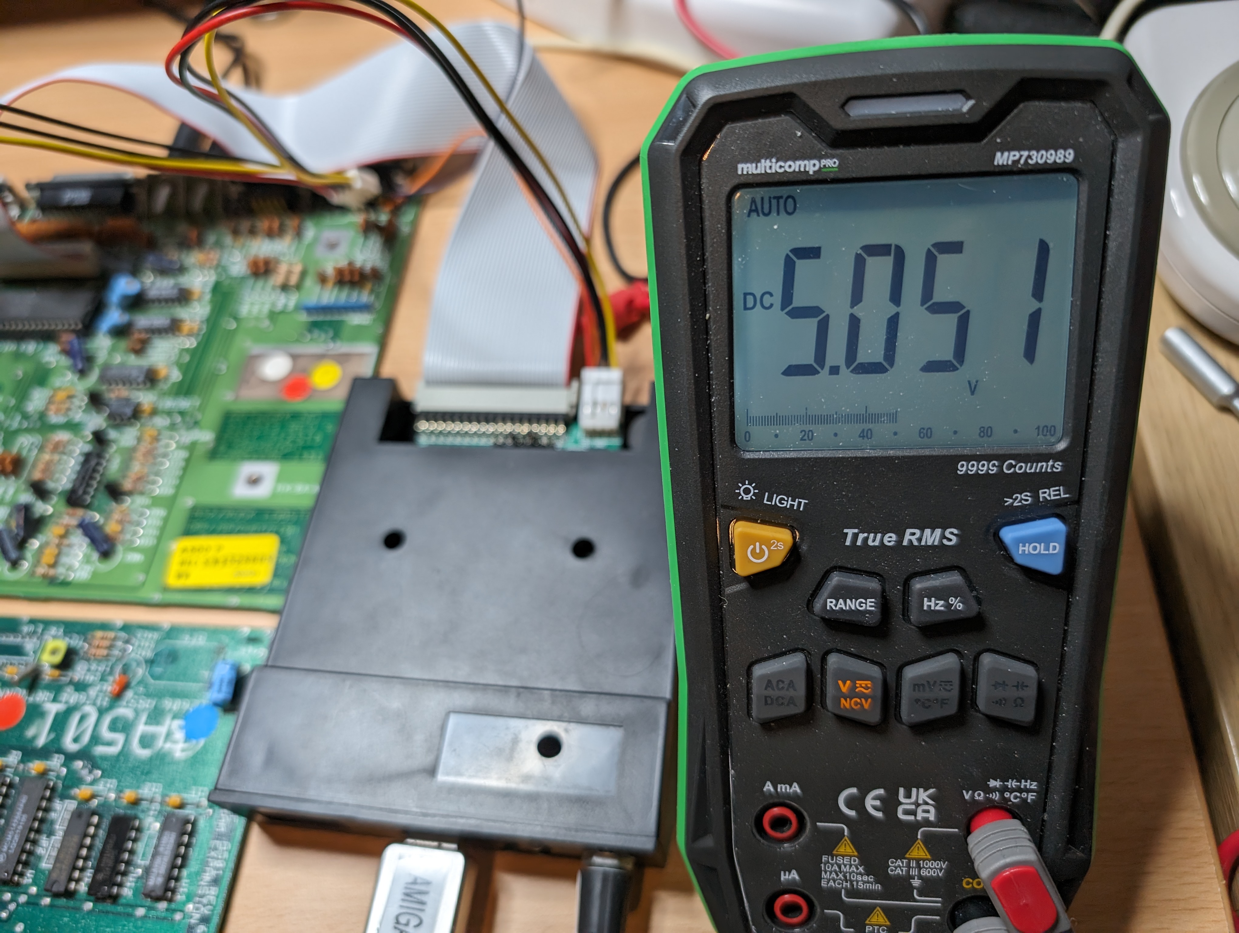
After a quick test of the voltages, I plugged it into my test motherboard to see if it works.

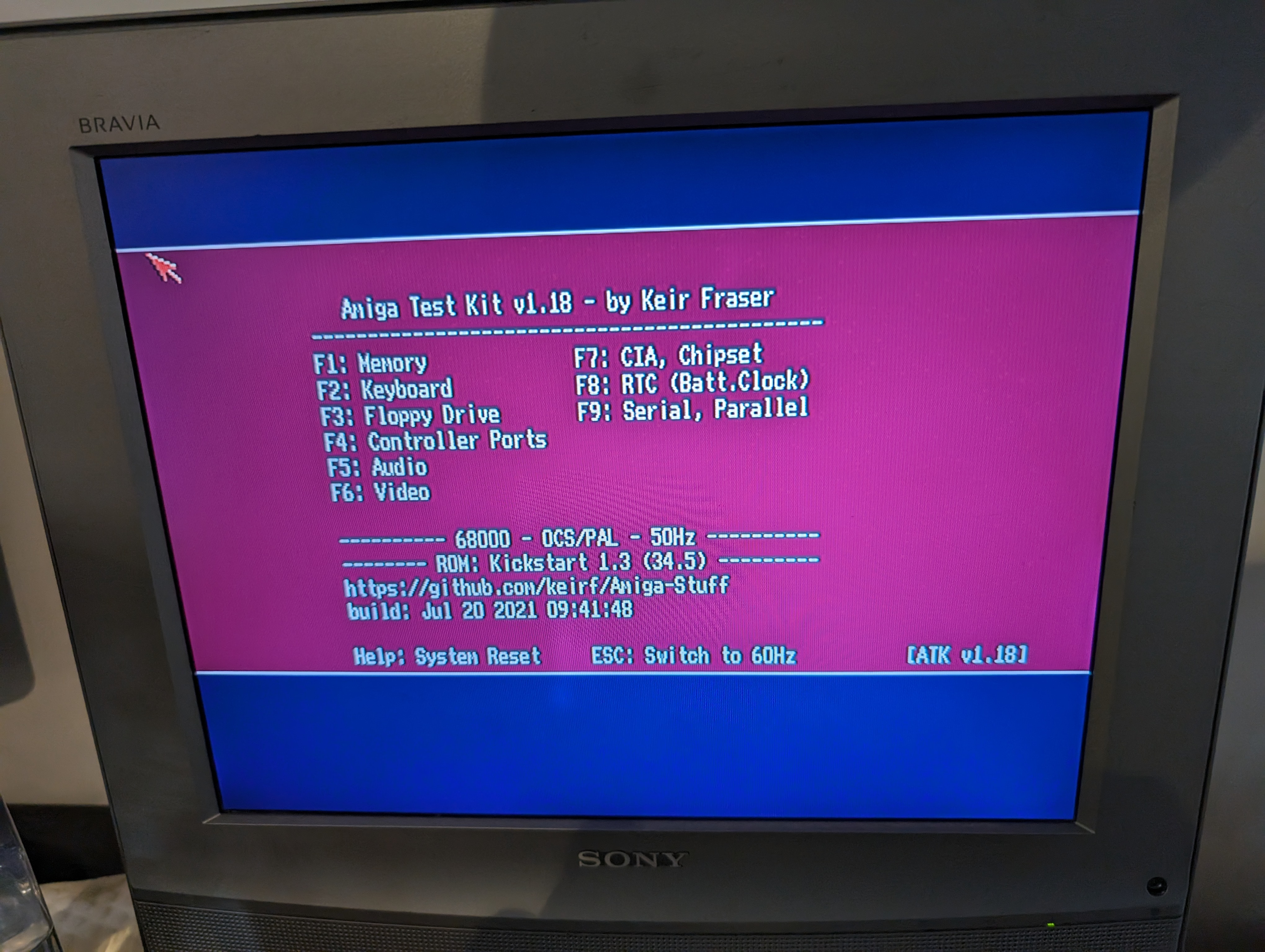
Perfect! It looks and sounds great. I now have a bit more of a beefy PSU when I need to power upgraded machines!


Leave a comment