
Many modern Amiga cards use Xilinx chips for everything from a basic CPLD for auto configuration to full blown CPU replacements. My Terrible Fire 534 accelerator has two of these chips and they are field programmable using JTAG. It turns out a Raspberry Pi can be turned into a programmer for these, so this is how to do it.
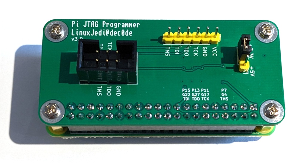
Update 2022-10-02: I have designed a Pi JTAG board to make the wiring even easier with protection voltage translators for the Pi. It is available here.
Update 2021-12-04: I have written an updated version of this post covering the new Bullseye version of Raspbian and other updates here.
First of all you need a Raspberry Pi, preferably not version 4. There are ways to make this work with v4 but I haven’t tried them, I’m told they are slower too. I happened to have a spare Pi Zero W which I bought for another project. It needed the GPIO pins soldered on and I have some spare right-angle ones from a previous Amiga repair, so I soldered these on.
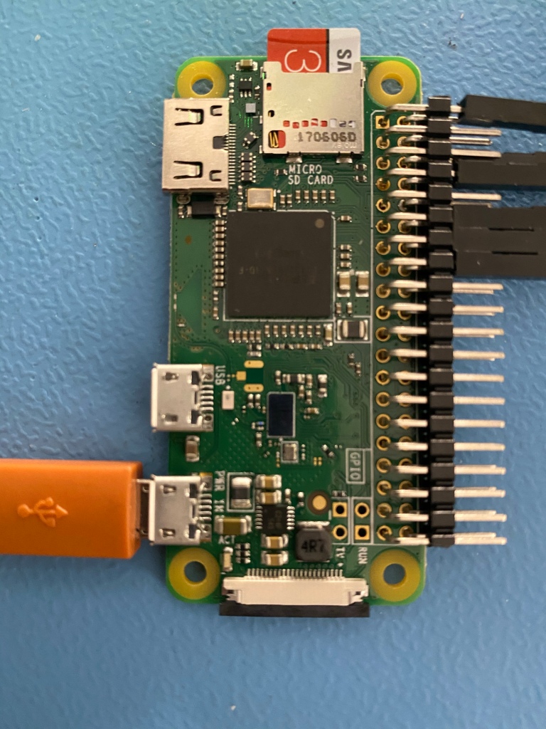
The SD card was flashed with Raspbian Lite and setup with SSH access so I could remote into it from my laptop to manage things.
We then need to build the programming software, this is a fork of xc3sprog that supports Raspberry Pi:
sudo apt update
sudo apt install build-essential libusb-dev libftdi-dev libgpiod-dev wiringpi git cmake
git clone https://github.com/matrix-io/xc3sprog
mkdir xc3sprog/build
cd xc3sprog/build
cmake ..
make
sudo make install
UPDATE 2021-11-25: The latest Raspbian Bullseye removed “wiringpi” from its repositories. This will cause the “apt” line above to file. If you are using Bullseye remove “wiringpi” from the “apt” line above and install it using the instructions found here.
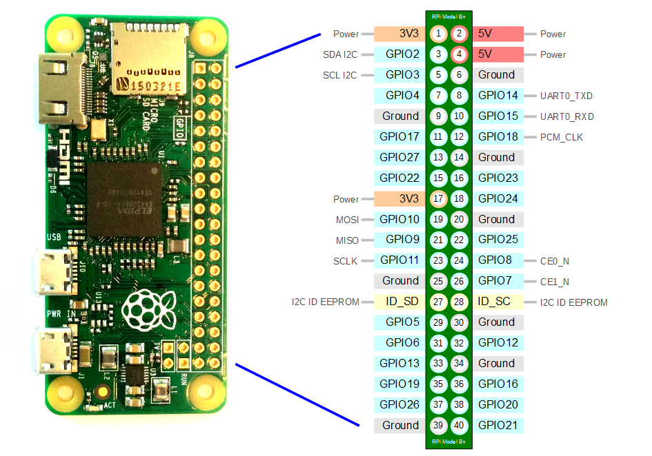
Finally we have to wire everything up. Use this table for the wiring map, I also used some very large wire tag labels to label each end.
| Pin | JTAG |
| 1 (or pin 17) | 3V3 |
| 6 (or any Ground pin) | GND |
| 7 | TMS |
| 11 | TCK |
| 13 | TDO |
| 15 | TDI |
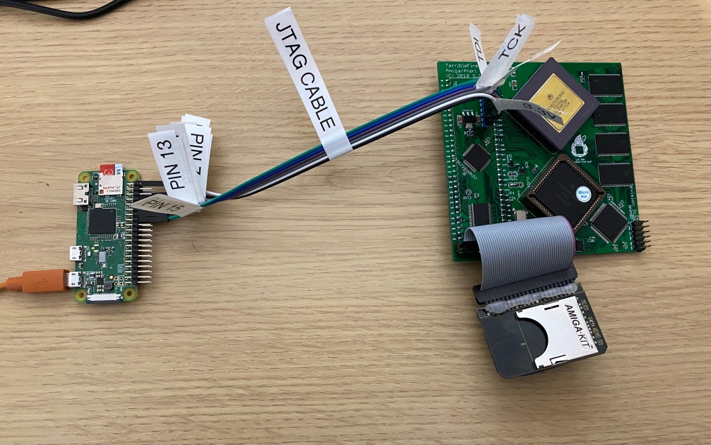
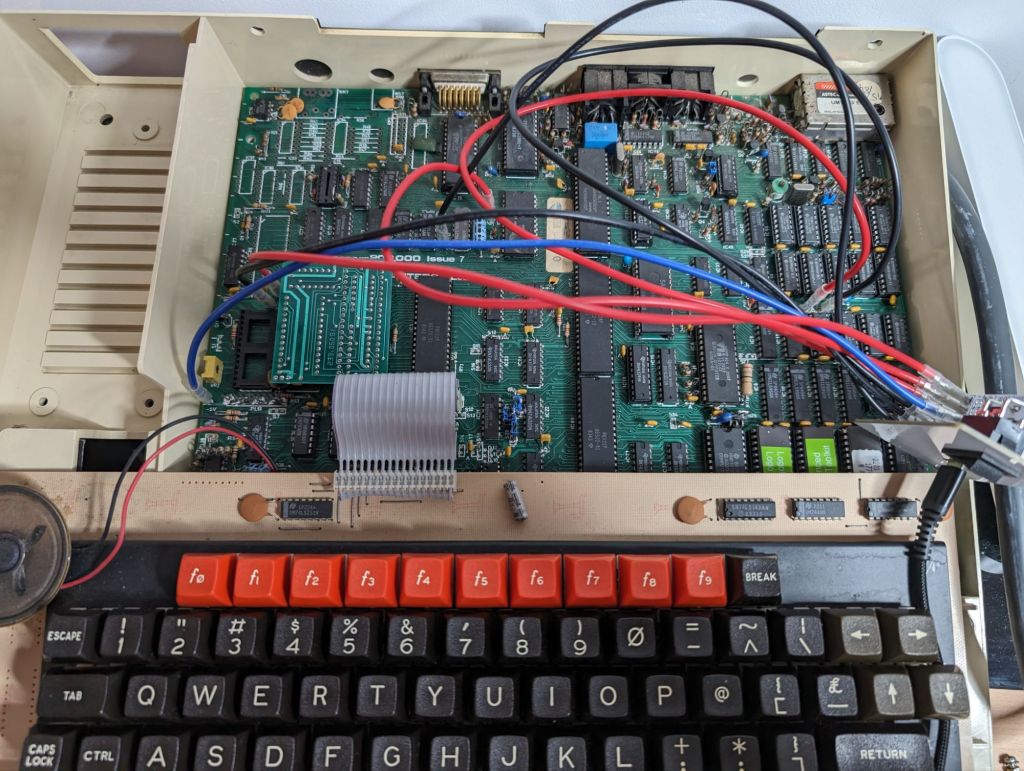
When wired up to the TF534 it looks a little like this:
Once we have both ends wired up, it is a case of running it. The following command should list all the chips in the JTAG chain, the TF534 has two of them. The “matrix_creator” uses WiringPi to talk to the JTAG:
xc3sprog -c matrix_creator -j
If you wish to download a Xilinx binary to your hard drive you can run the following (assuming you want to talk to item 1 in the chain). The “:r” part at the end means read the chip to file instead of write from file:
xc3sprog -c matrix_creator -v -p 1 myxilinx.jed:r
Finally to write a new image to the Xilinx (again to item 1 in the chain):
xc3sprog -c matrix_creator -v -p 1 newxilinx.jed
You should see something similar to this (screenshot from programming the TF534):
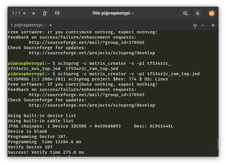
It all worked out really well and I now have a Xilinx programmer I can use for an upcoming project!

Leave a comment