

In my previous post, I mentioned that I managed to get the SSD1351 working with a Raspberry Pi Pico. I figured I would write a few blog posts going into detail about how this is done.
In this first post, I’ll talk about how to talk to the SSD1351 OLED display. You’ll find that many OLED and LCD displays are very similar in this regard so it can be an excellent introduction to talking about displays in general.
Hardware
The SSD1351 is a controller chip inside colour OLED displays that are usually 128×128 pixels and usually 1.5″ in size. By default, it is 16 bits per pixel for colour. But wait… How does 16 divide by 3 for the three different colours? Well, it doesn’t. The colour format is RGB565 which is 5 bits for red, 6 bits for green and 5 bits for blue. It makes sense to put the extra bit to green because as humans our eyes can typically detect more levels of green than red and blue. So, a full frame is 128x128x2 bytes = 32KB.
There are a few different ways to talk to the display, but I will focus on SPI, a high-speed serial interface. We are not using full SPI here, which is one wire per direction, the display as we use it here is write-only. In SPI mode we have the following pins:
| Label | Description |
|---|---|
| GND | Ground pin |
| VCC | +3.3v pin |
| SCL | Serial clock pin |
| SDA | Serial data pin |
| RES | Reset pin |
| DC | Data / Command pin |
| CS | Chip select pin |
The serial data is synchronised to the clock as is standard for the SPI protocol. The RES pin resets the display’s controller when it is low. The DC should be set low for a command being sent and high for data being sent. The CS should be set low otherwise the controller will ignore the data. This is so that you can have multiple devices on the SPI bus.
So, how do we hook this up to the Pi Pico? Here is a diagram of the Pico.
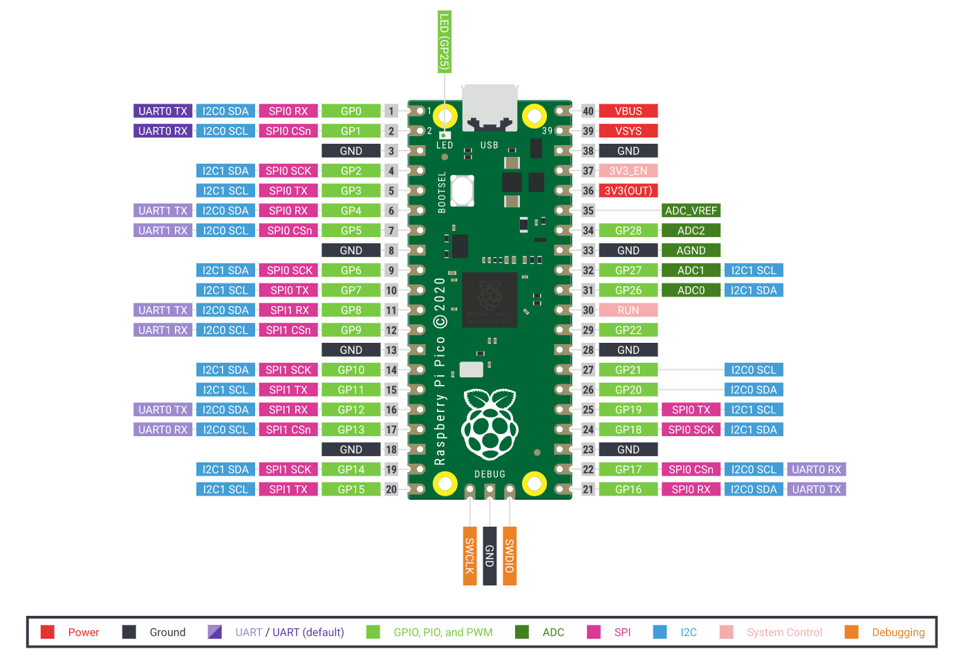
You can see here the Pico has two SPI channels and you can choose which pins you want to use for each channel out of a range of them. The key ones to hook up are an SCK to the SCL of the display, TX to the SDA of the display, pick any GPIO pins for RES and DC and tie CS to GND. You can power the display from the 3V3(OUT) pin of the Pico.
Software
For this, I’m going to be talking about how to interface in C using the Pico SDK. You can of course use an off-the-shelf library. But I did everything from scratch. The datasheet for the display can be found all over the web and is very useful here.
The first thing we need to do is set up the SPI connection, this is done as follows:
#define SPI_NUM   spi0
#define SPI_DC    5
#define SPI_RST   4
#define SPI_SCK   6
#define SPI_DATA  7
#define SPI_SPEED 20000000 // 20MHz, about the limit in tests

void ssd1351_init()
{
   // Setup SPI
    spi_init(SPI_NUM, SPI_SPEED);
    spi_set_format(SPI_NUM, 8, SPI_CPOL_1, SPI_CPHA_1, SPI_MSB_FIRST);
    gpio_set_function(SPI_SCK, GPIO_FUNC_SPI);
    gpio_set_function(SPI_DATA, GPIO_FUNC_SPI);

    // Setup GPIO
    gpio_init(SPI_DC);
    gpio_set_dir(SPI_DC, GPIO_OUT);
    gpio_put(SPI_DC, 1);

    gpio_init(SPI_RST);
    gpio_set_dir(SPI_RST, GPIO_OUT);
}
We are setting the SPI to 20MHz, so for a 32KB frame we can, in theory, do 76 frames per second, the reality is slightly lower due to things like command overhead, but for a tiny display like this, it is more than fast enough. The numbers used for the defined IOs are GPIO numbers, not pin numbers.
The spi_set_format() function outlines the number of bits per transfer, the polarity, phase and byte order.
Next up we need to reset the display, this can go at the end of our init function:
void ssd1351_init()
{
    ...

    // Power on reset
    gpio_put(SPI_RST, 1);
    sleep_ms(10);
    gpio_put(SPI_RST, 0);
    sleep_ms(500);
    gpio_put(SPI_RST, 1);
    gpio_put(SPI_DC, 0);
}
Then we need a function to write data to the SPI:
#define WRITE_COMMAND 0
#define WRITE_DATA 1

static void ssd1351_write(const uint8_t cmd, const uint8_t* data, size_t len)
{
    gpio_put(SPI_DC, WRITE_COMMAND);
    spi_write_blocking(SPI_NUM, &cmd, 1);
    if (len)
    {
        gpio_put(SPI_DC, WRITE_DATA);
        spi_write_blocking(SPI_NUM, data, len);
    }
}
This basically sets DC into command mode, sends the command byte, then if there is data it sets DC to data mode and sends the associated data.
We then have to send a bunch of commands to initialise the display itself. I won’t go into detail here about what each of these do, some of them I’ve put in the code comments, but you can look them up in the SSD1351 datasheet.
#define SSD_CMD_COMMANDLOCK   0xFD
#define SSD_CMD_DISPLAYOFF    0xAE
#define SSD_CMD_CLOCKDIV      0xB3
#define SSD_CMD_MUXRATIO      0xCA
#define SSD_CMD_SETREMAP      0xA0
#define SSD_CMD_STARTLINE     0xA1
#define SSD_CMD_DISPLAYOFFSET 0xA2
#define SSD_CMD_SETGPIO       0xB5
#define SSD_CMD_FUNCTIONSEL   0xAB
#define SSD_CMD_NONINVERT     0xA6
#define SSD_CMD_CONTRASTABC   0xC1
#define SSD_CMD_CONTRASTMASTER 0xC7
#define SSD_CMD_ENHANCE       0xB2
#define SSD_CMD_DISPLAYON     0xAF

void ssd1351_init()
{
    ...

    // Init display

    // Unlock driver
    param[0] = 0x12;
    ssd1351_write(SSD_CMD_COMMANDLOCK, param, 1);

    // Unlock commands
    param[0] = 0xB1;
    ssd1351_write(SSD_CMD_COMMANDLOCK, param, 1);

    ssd1351_write(SSD_CMD_DISPLAYOFF, NULL, 0);

    // Max frequency, no divider. Fastest refresh rate.
    param[0] = 0xF0;
    ssd1351_write(SSD_CMD_CLOCKDIV, param, 1);

    // Effectively number of lines
    param[0] = 0x7F;
    ssd1351_write(SSD_CMD_MUXRATIO, param, 1);

    // Horizontal addressing, unmirrored, C->B->A colours, normal scan, 65K colours
    param[0] = 0x74;
    ssd1351_write(SSD_CMD_SETREMAP, param, 1);

    param[0] = 0x00;
    ssd1351_write(SSD_CMD_STARTLINE, param, 1);

    param[0] = 0x00;
    ssd1351_write(SSD_CMD_DISPLAYOFFSET, param, 1);

    // Disable GPIO
    param[0] = 0x00;
    ssd1351_write(SSD_CMD_SETGPIO, param, 1);

    // 16bit parallel interface
    param[0] = 0x01;
    ssd1351_write(SSD_CMD_FUNCTIONSEL, param, 1);

    ssd1351_write(SSD_CMD_NONINVERT, NULL, 0);

    // R G B contrast
    param[0] = param[1] = param[2] = 0xFF;
    ssd1351_write(SSD_CMD_CONTRASTABC, param, 3);

    // Max master contrast
    param[0] = 0x0F;
    ssd1351_write(SSD_CMD_CONTRASTMASTER, param, 1);

    param[0] = 0xA4;
    param[1] = 0x00;
    param[2] = 0x00;
    ssd1351_write(SSD_CMD_ENHANCE, param, 3);

    ssd1351_write(SSD_CMD_DISPLAYON, NULL, 0);
}
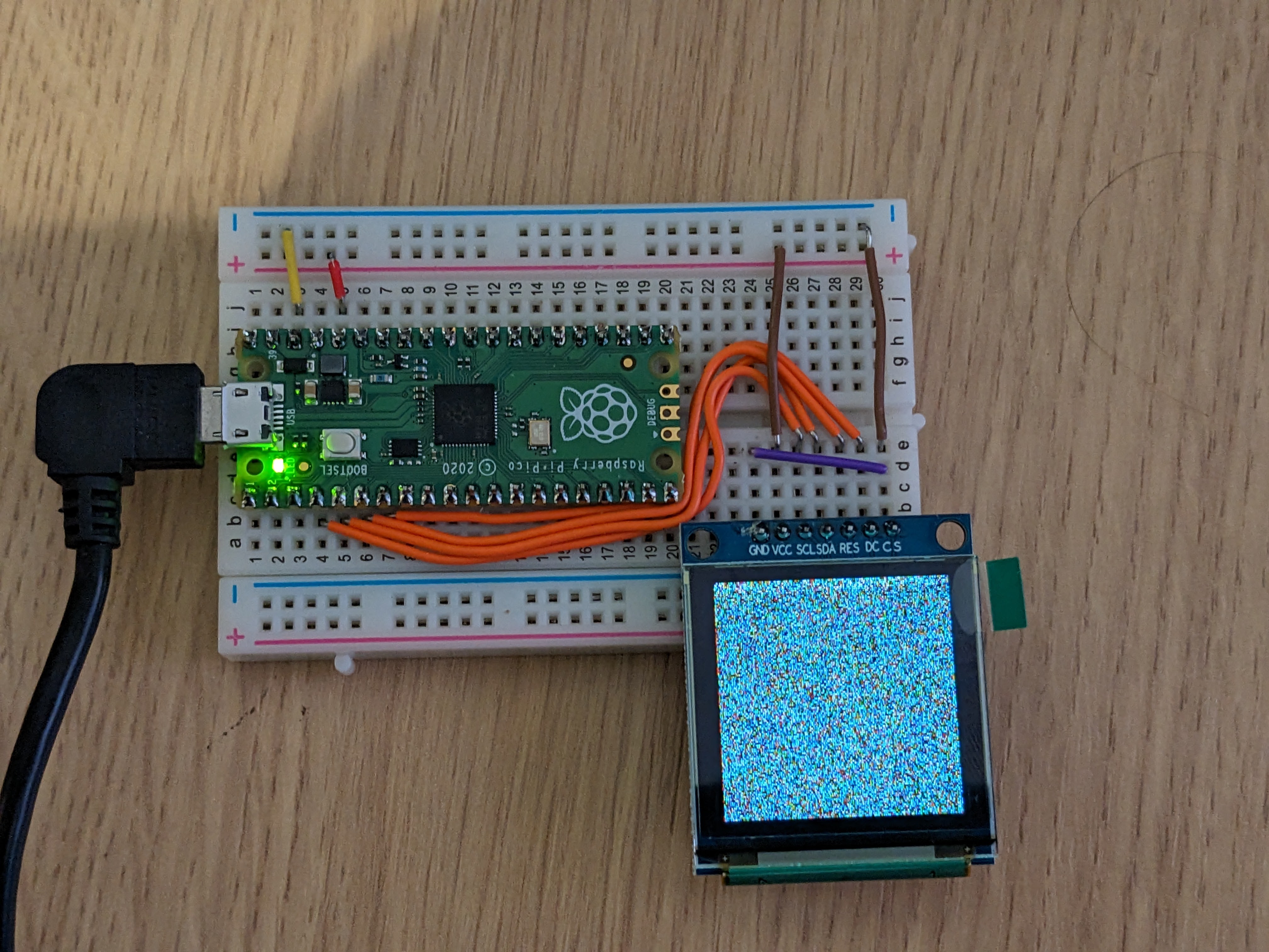
Now the display is ready to use, if you execute the program here then you will get a display of random colour pixels due to the power-on randomness of the RAM. This is a good sign that you were able to configure the display correctly.
We need to be able to send images, but we can make the image transfers really fast. So let’s do that!
DMA Transfers
The Pi Pico supports DMA transfers which can transfer between the memory and something else freeing up the main CPU cores for other tasks. This means we can set up a frame buffer in memory, point that memory at the SPI and say “Go!” and then can get on with other tasks. This also means we need two frame buffers, the one currently being sent to the display and the next one being calculated by the CPU, otherwise, we will get some weird effects as the current buffer being sent is modified. Alternatively, we have to wait until the frame has been sent via DMA before we start calculating the next one, which defeats the purpose of using it.
To initialise DMA transfers we set it up like this:
#define WIDTH 128
#define HEIGHT 128

uint8_t oled_dma_1[HEIGHT * WIDTH * 2] = {0x00};
uint8_t oled_dma_2[HEIGHT * WIDTH * 2] = {0x00};

static volatile uint dma_tx;
static dma_channel_config config;

void ssd1351_init()
{
    ...
    dma_tx = dma_claim_unused_channel(true);
    config = dma_channel_get_default_config(dma_tx);
    channel_config_set_transfer_data_size(&config, DMA_SIZE_8);
    channel_config_set_dreq(&config, spi_get_index(SPI_NUM) ? DREQ_SPI1_TX : DREQ_SPI0_TX);
    dma_channel_configure(dma_tx, &config, &spi_get_hw(SPI_NUM)->dr, oled_dma_1, sizeof(oled_dma_1), false);
}
Here we are grabbing a free DMA channel, and configuring it to write to the SPI. Although we are pointing to oled_dma_1, this is actually redundant at this point, we will change which buffer we are pointing to at transfer time.
Now to send data to the DMA we need two functions, one to do the flushing and one to do the buffer swap. So it goes a little something like this:
#define SSD_CMD_WRITERAM      0x5C

uint8_t current_buffer = 1;

static void ssd1351_flush_dma(uint8_t *ptr, size_t len)
{
    // It is possible to call this whilst the DMA is still dumping the previous
    // frame. This blocks until we are ready to start the next frame.
    dma_channel_wait_for_finish_blocking(dma_tx);
    // 1ms pause because otherwise we can flip from data of the previous frame
    // to command of this one too quickly.
    sleep_ms(1);
    ssd1351_write(SSD_CMD_WRITERAM, NULL, 0);

    gpio_put(SPI_DC, WRITE_DATA);

    dma_channel_transfer_from_buffer_now(dma_tx, ptr, len);
}

void ssd1351_refresh()
{
    // Flush one buffer to the DMA, copy it to the other buffer and set that
    // one as the current one to write modify.
    if (current_buffer == 1)
    {
        ssd1351_flush_dma(oled_dma_1, sizeof(oled_dma_1));
        memcpy(oled_dma_2, oled_dma_1, sizeof(oled_dma_1));
        current_buffer = 2;
    }
    else
    {
        ssd1351_flush_dma(oled_dma_2, sizeof(oled_dma_2));
        memcpy(oled_dma_1, oled_dma_2, sizeof(oled_dma_2));
        current_buffer = 1;
    }
}
The application will call the ssd1351_refresh() function when it is ready to send the buffer to the screen. This first calls the ssd1351_flush_dma() function and the first thing that does is wait if there is an ongoing DMA transfer. This is because DMA transfers happen asynchronously in the background and most of the time the next frame will be ready before the first frame has been fully transferred. There is also a tiny pause afterwards otherwise the timing of the flip of the DC pin causes corruption.
Next, we send the command to say “Hey! I’m about to send a buffer over to you”, and then we tell the DMA channel to transfer from the current buffer. This will happen in the background and return immediately.
Back to ssd1351_refresh() and we copy the buffer over to the other one so that changes can be made to the image between frames, store an ID for the current buffer the application is writing to, and let everything continue.
One key thing to remember is if we want to send any other commands to the display, we need to block waiting for the DMA transfer to finish first followed by the 1ms pause.
Next Steps
So, we now have everything you need to send commands and frames to the display. In my next post, I’ll show you some tricks you can do to manipulate the display buffers. In the meantime, the source code for this can be obtained here.
Leave a Reply