

With a clean motherboard base to work from, it is time to start the repair work!
Battery Damage Diagnosis
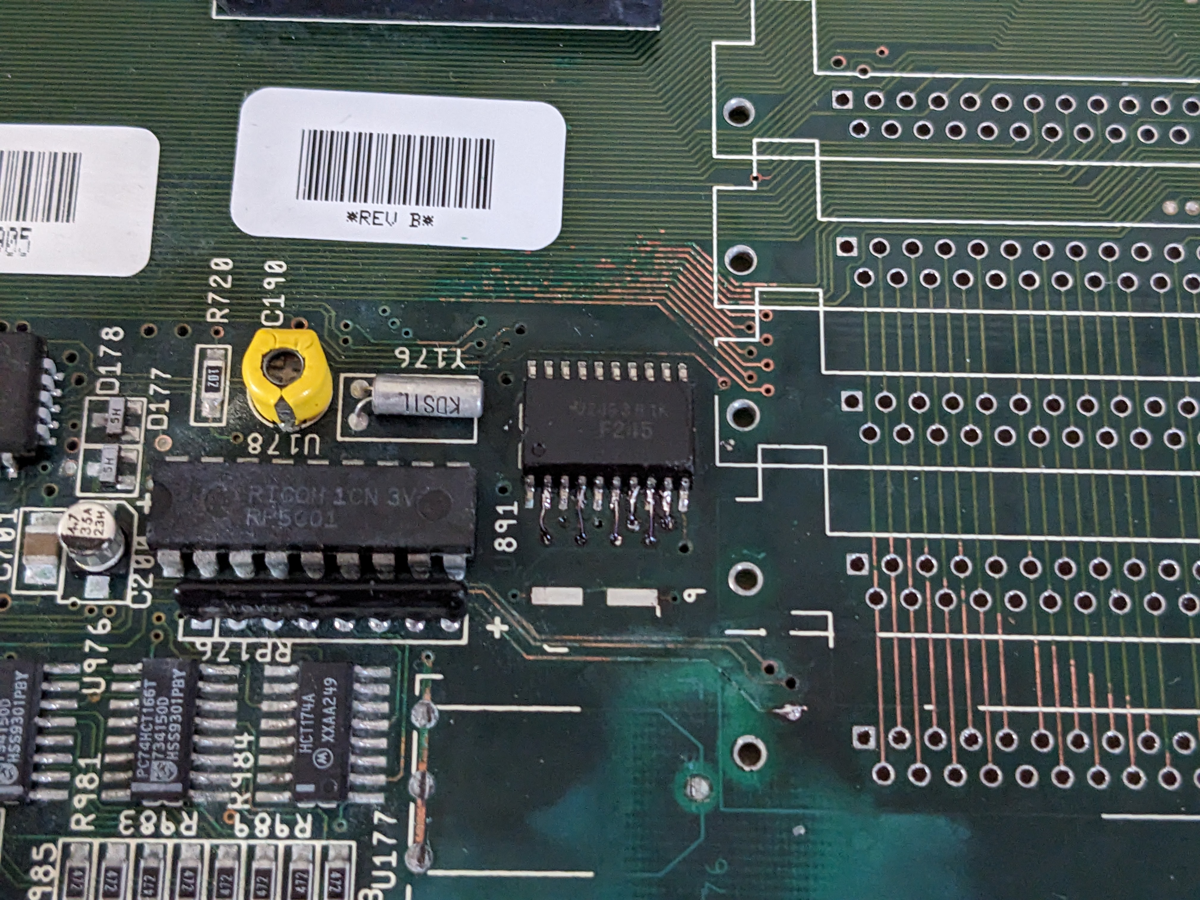
Using a multimeter in continuity mode, I worked out where all the obvious broken traces were. It seems the damage was not as bad as I anticipated. I found 6 failed vias around U891 and the trace for the R/W signal to the Fast RAM area.
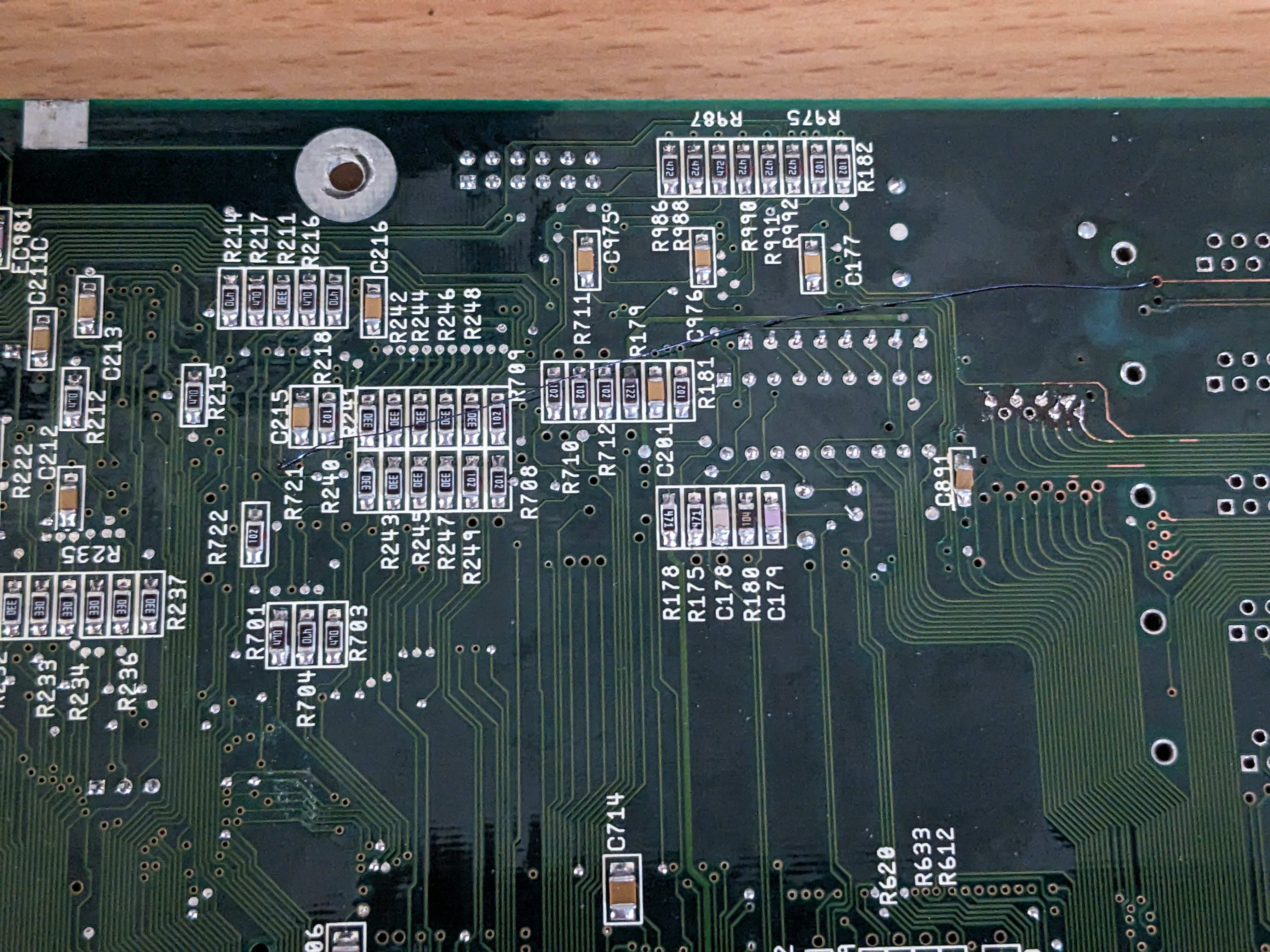
Not my finest work, but everything appears to be connected correctly now.
Capacitor Removal
The surface mount capacitors showed signs of leakage, so I removed them all to test them. I remove them using a “duel-wield” technique, using two soldering irons, one on each side to remove each capacitor. I then used a Peak ESR meter to test each capacitor. ESR stands for Equivalent Series Resistance. The ideal is to get this as near to zero as possible, if it is too high, then it will be slow to react to oscillations. Most capacitors are there to respond to oscillations and fluctuations in voltage. Therefore, a low ESR is essential.
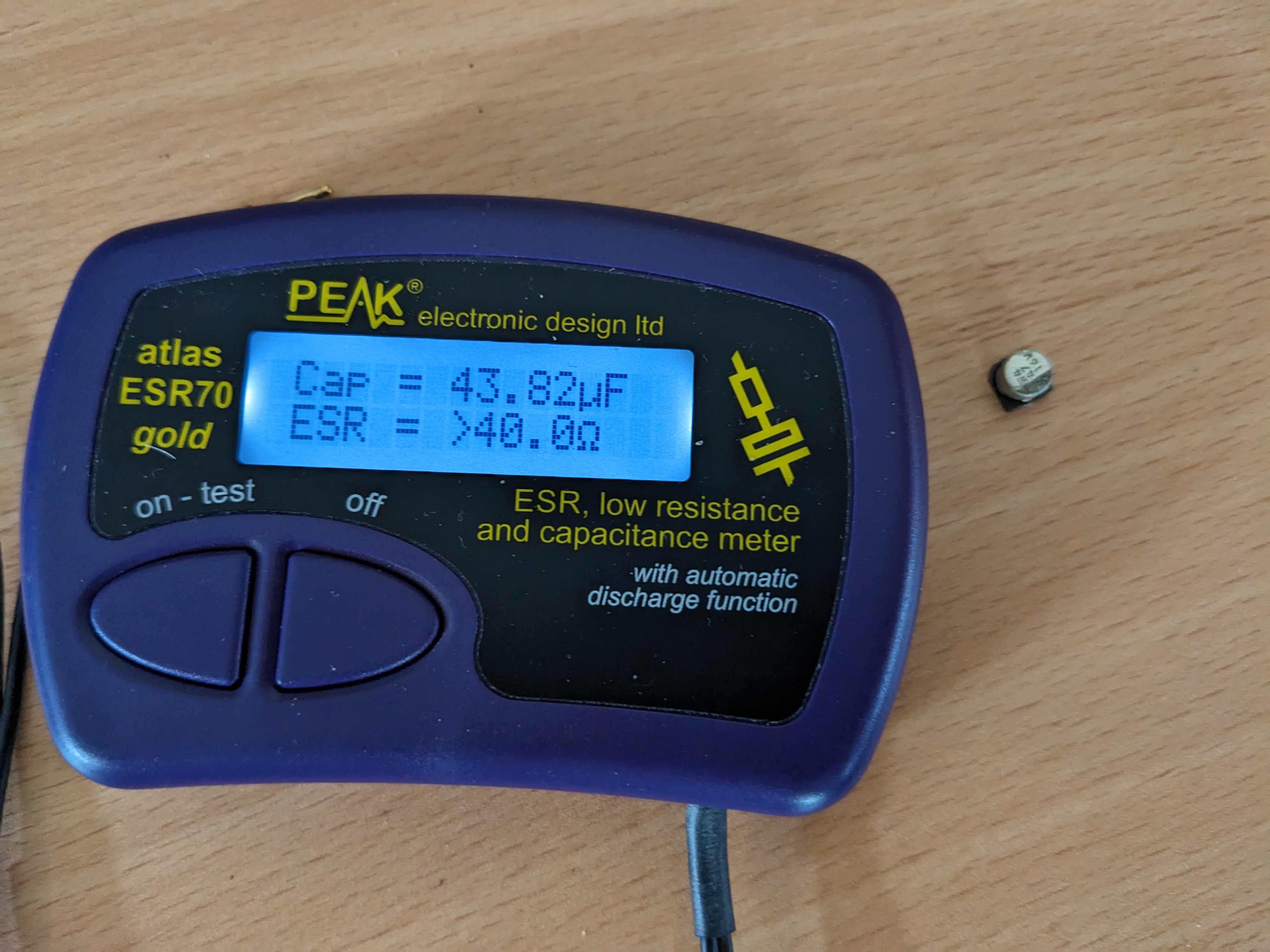
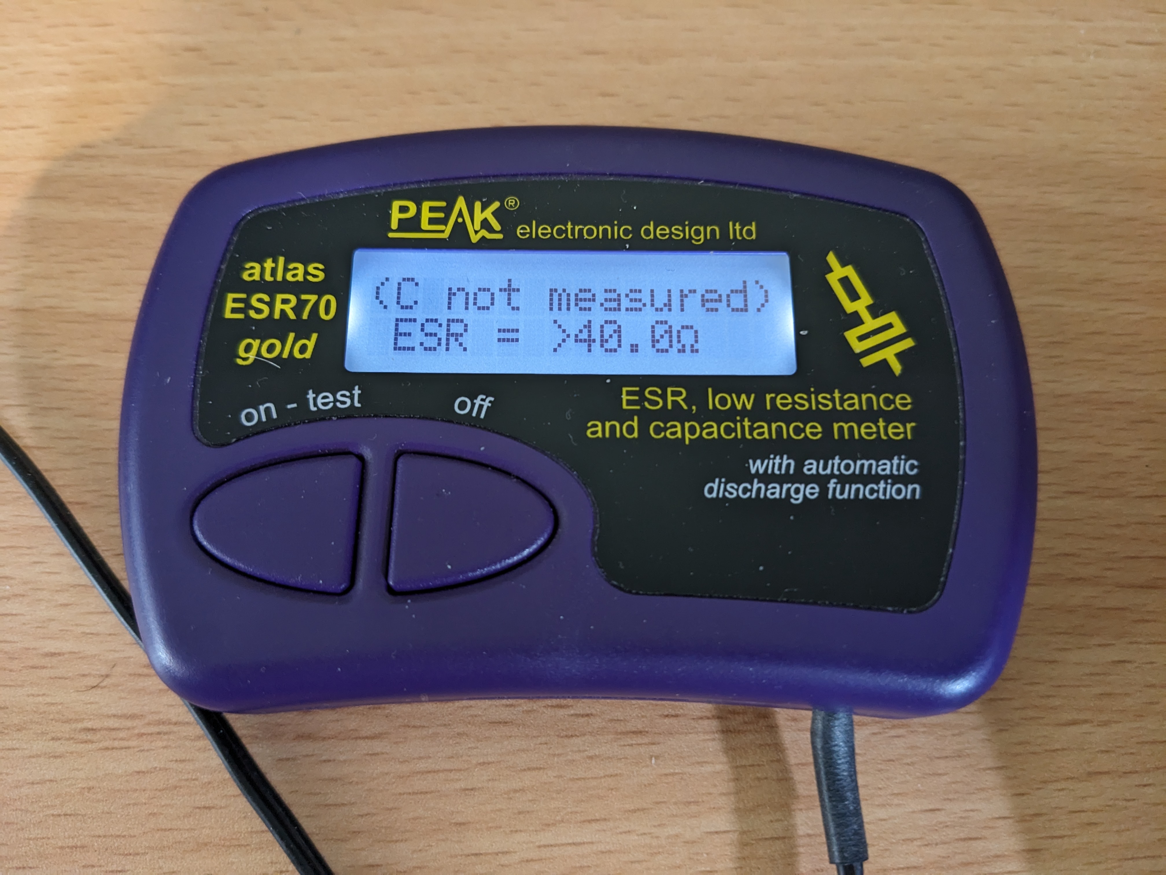
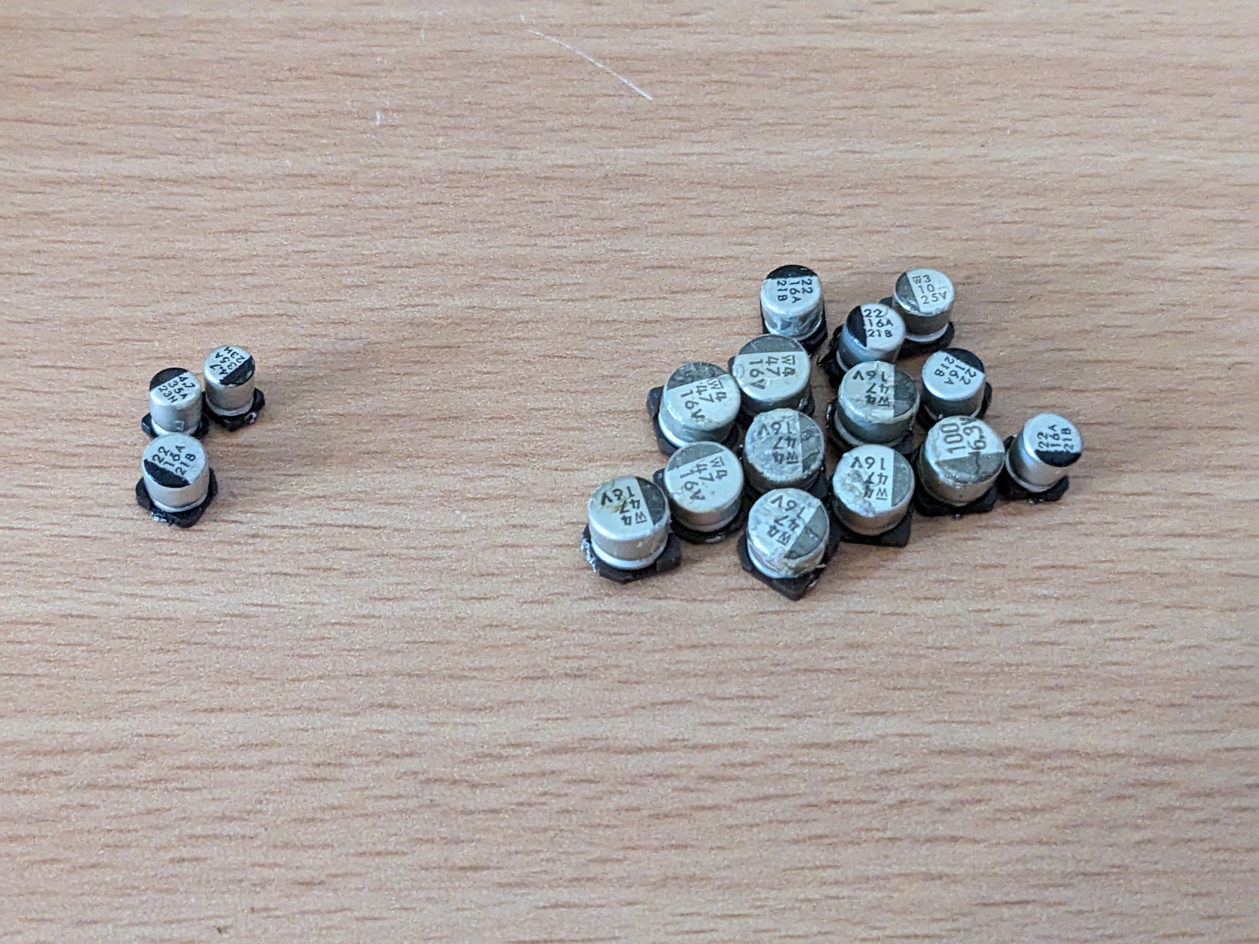
Pretty much all the capacitors had failed. The ones on the left had values and ESRs within tolerable ranges. All the capacitors on the right had ESRs significantly out of range, many could not read a capacitance value either. They will all be replaced with brand-new ones.
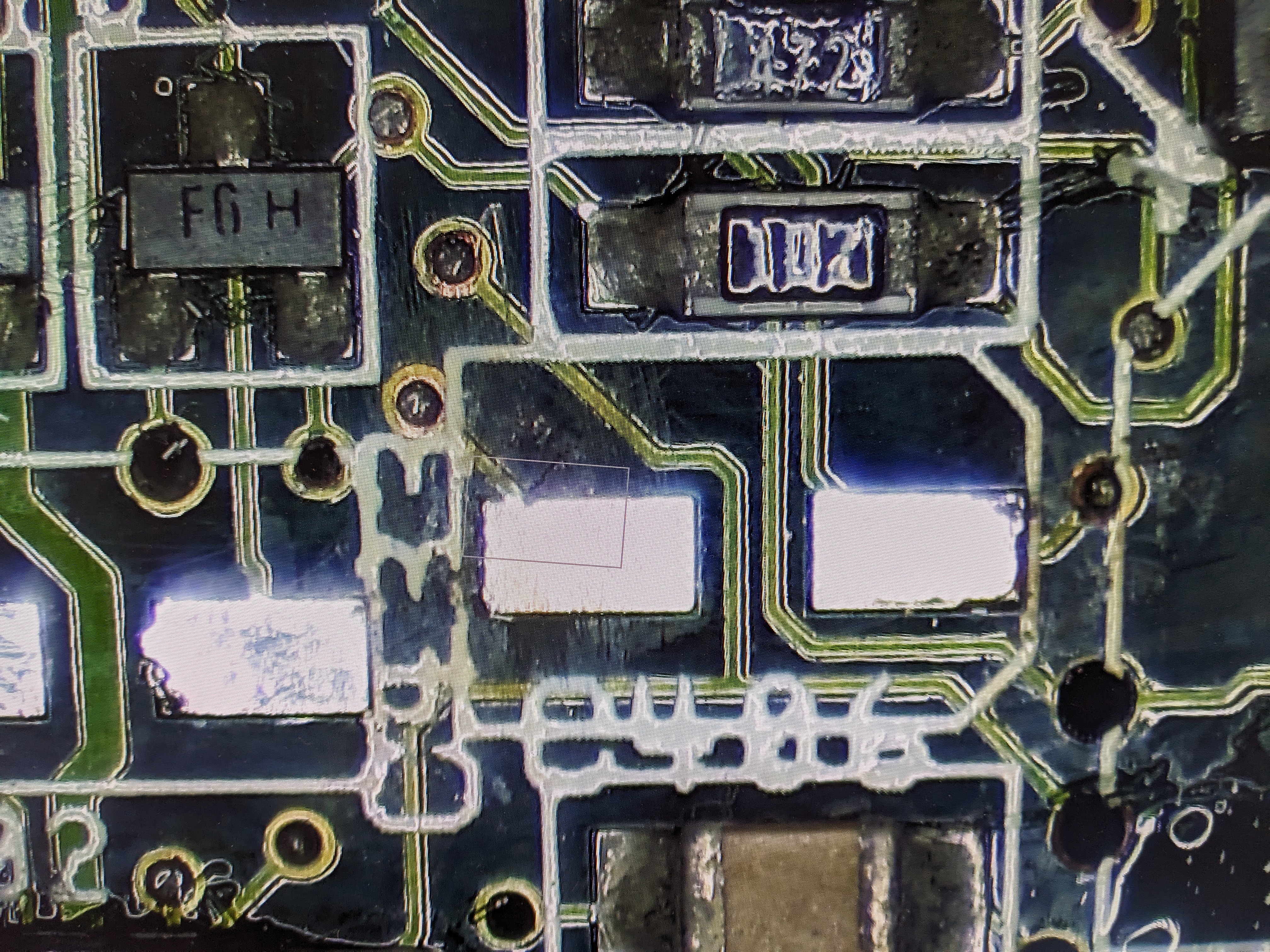
When I removed them, I found some black scaring near a pad of one of the capacitors. I was concerned this was some damage to the PCB caused by the capacitor.
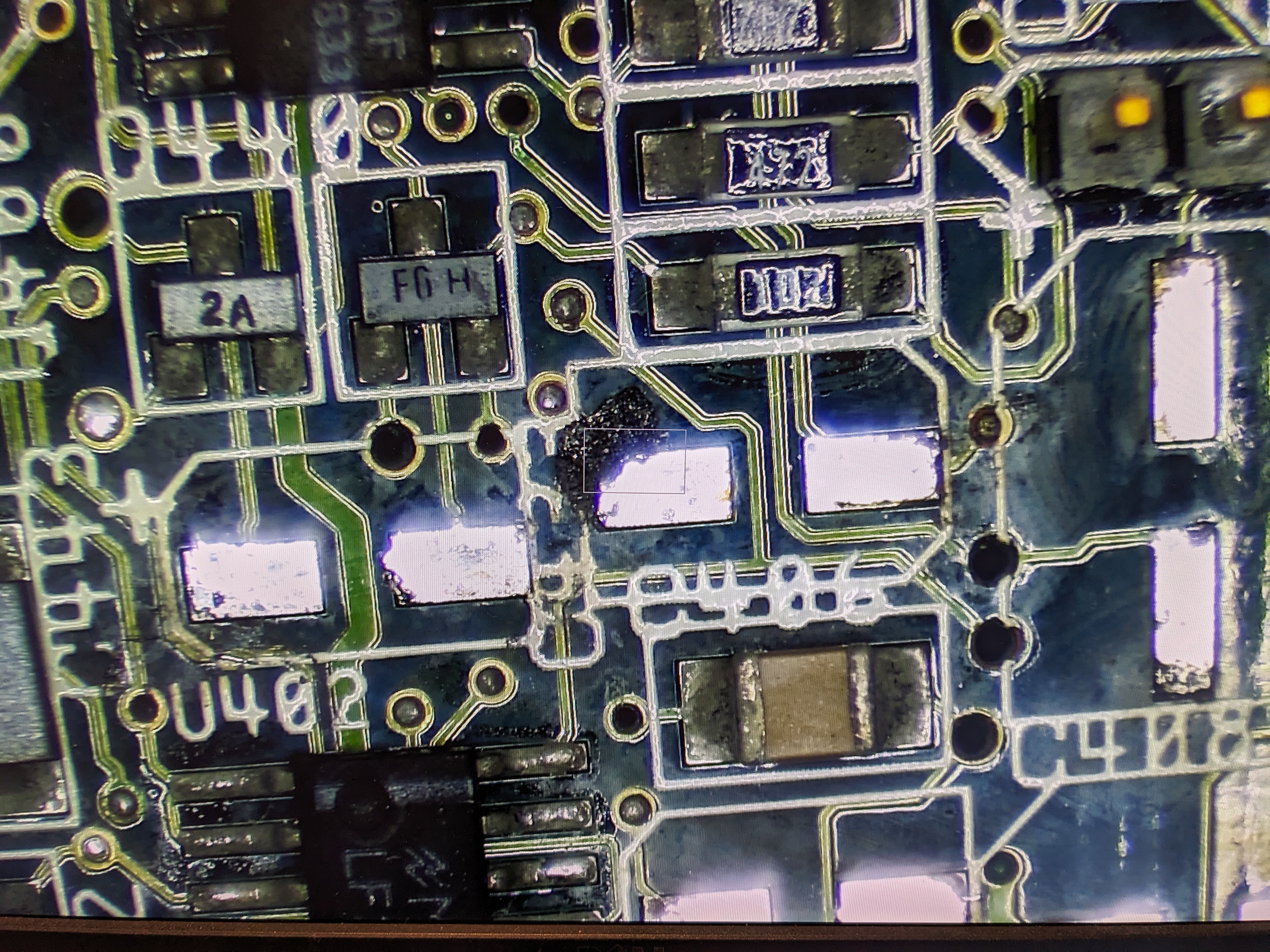
It turns out that there was still continuity there, so the black mark must be crusting on top. Sure enough, with a little abrasion, it came away.
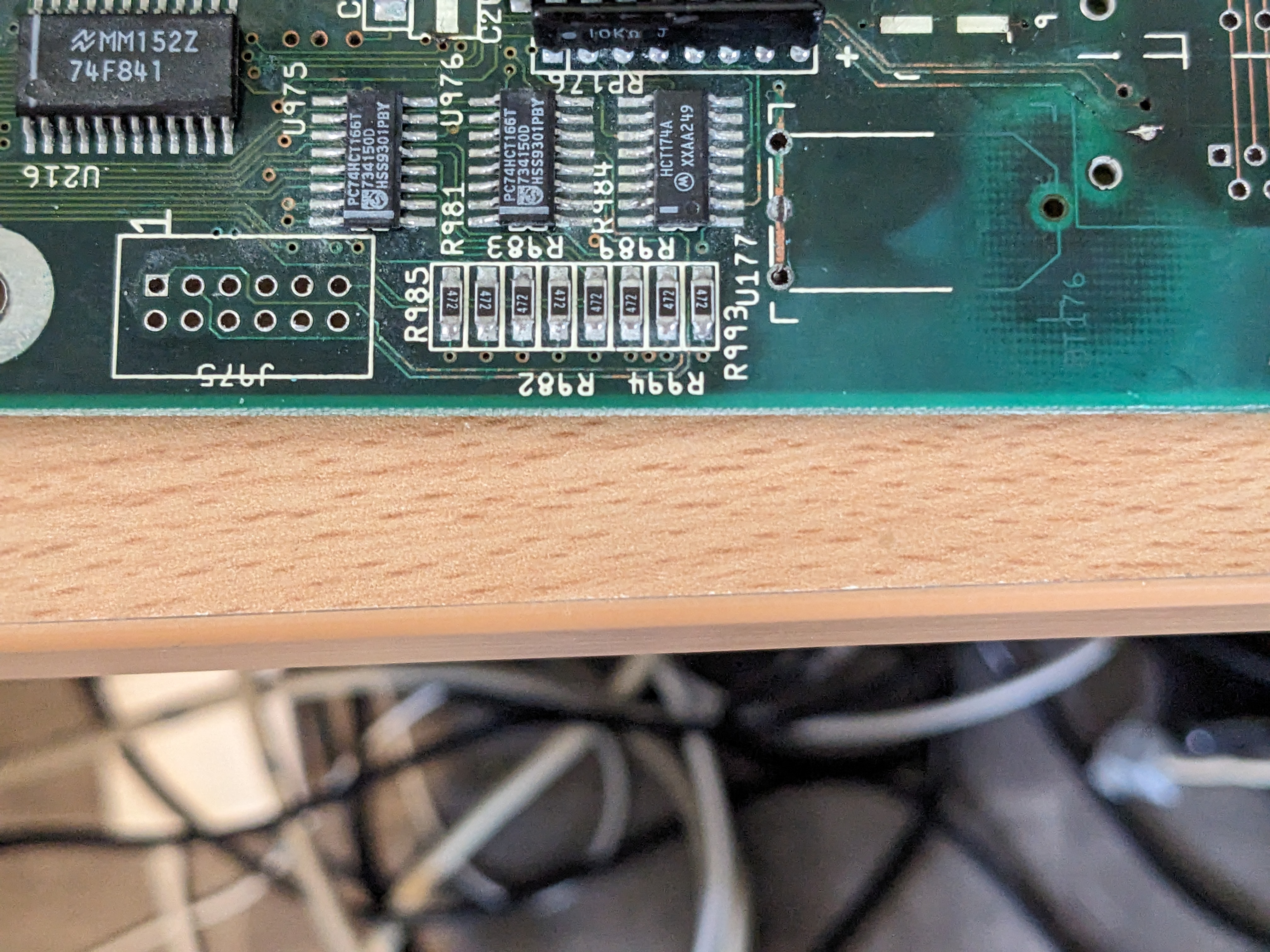
The pads and connections for all the other capacitors were still in a good state.
Whilst I was at it, I also removed the remains of the battery legs and the corroded pin header.
More Parts Cleaning
The rear IO card mounting parts and mouse/joystick mount were in a bad need of a cleanup.
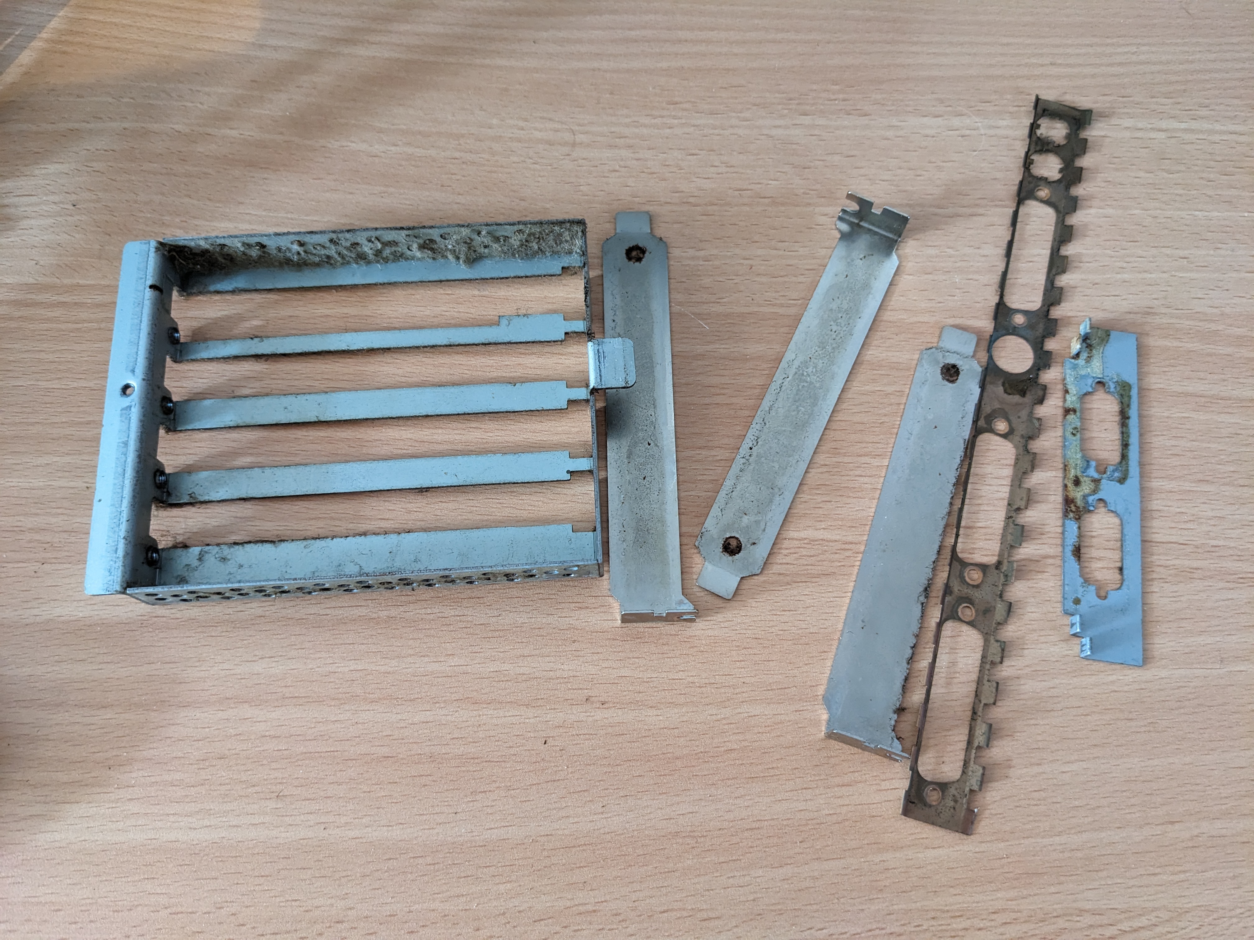
I put it all in the ultrasonic cleaners and for the mouse/joystick mount I also used a bit of abrasion with a wire brush afterwards to remove some of the corrosion.
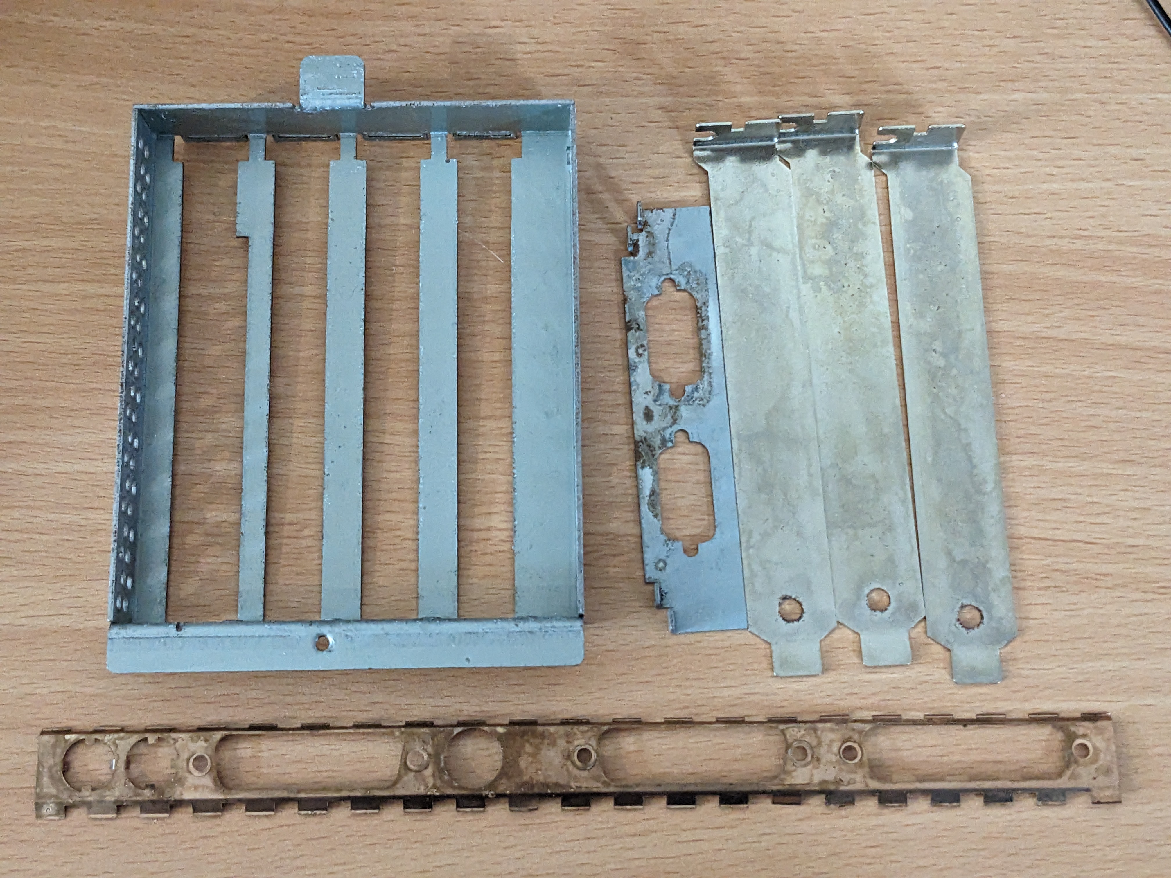
I could still probably remove some more of the corrosion, but it is certainly all looking quite a bit cleaner.
Capacitor Replacements
Now that the capacitors have been removed, the new ones could be fitted. One key thing I did was deliberately solder the audio capacitors backwards. This is because they were soldered the wrong way around on the original machine. It doesn’t affect things too much, but allows the capacitors to live a bit longer.

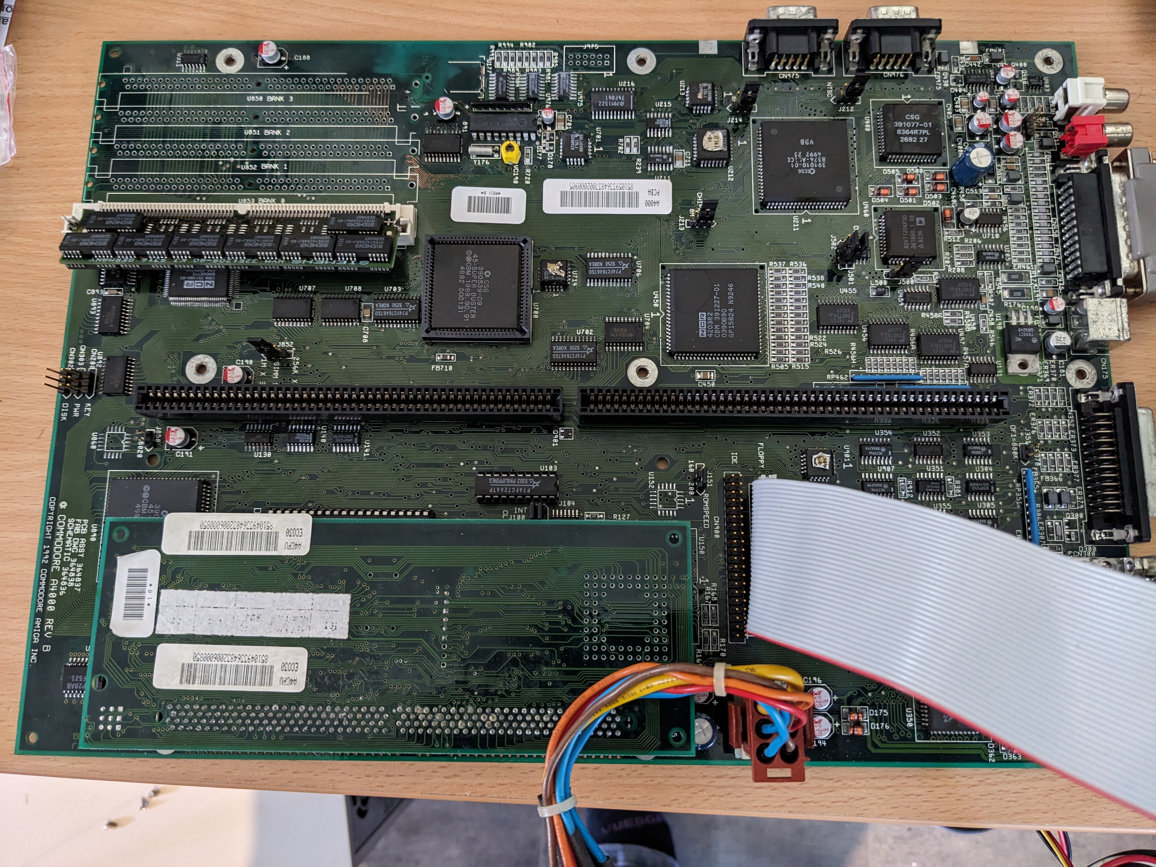
Whilst I was at it, I soldered the SIMM socket for the Chip RAM. This is the bare minimum needed to boot the machine.
Testing
I wired up everything that is a bare minimum to test the machine.
I turned it on, and…
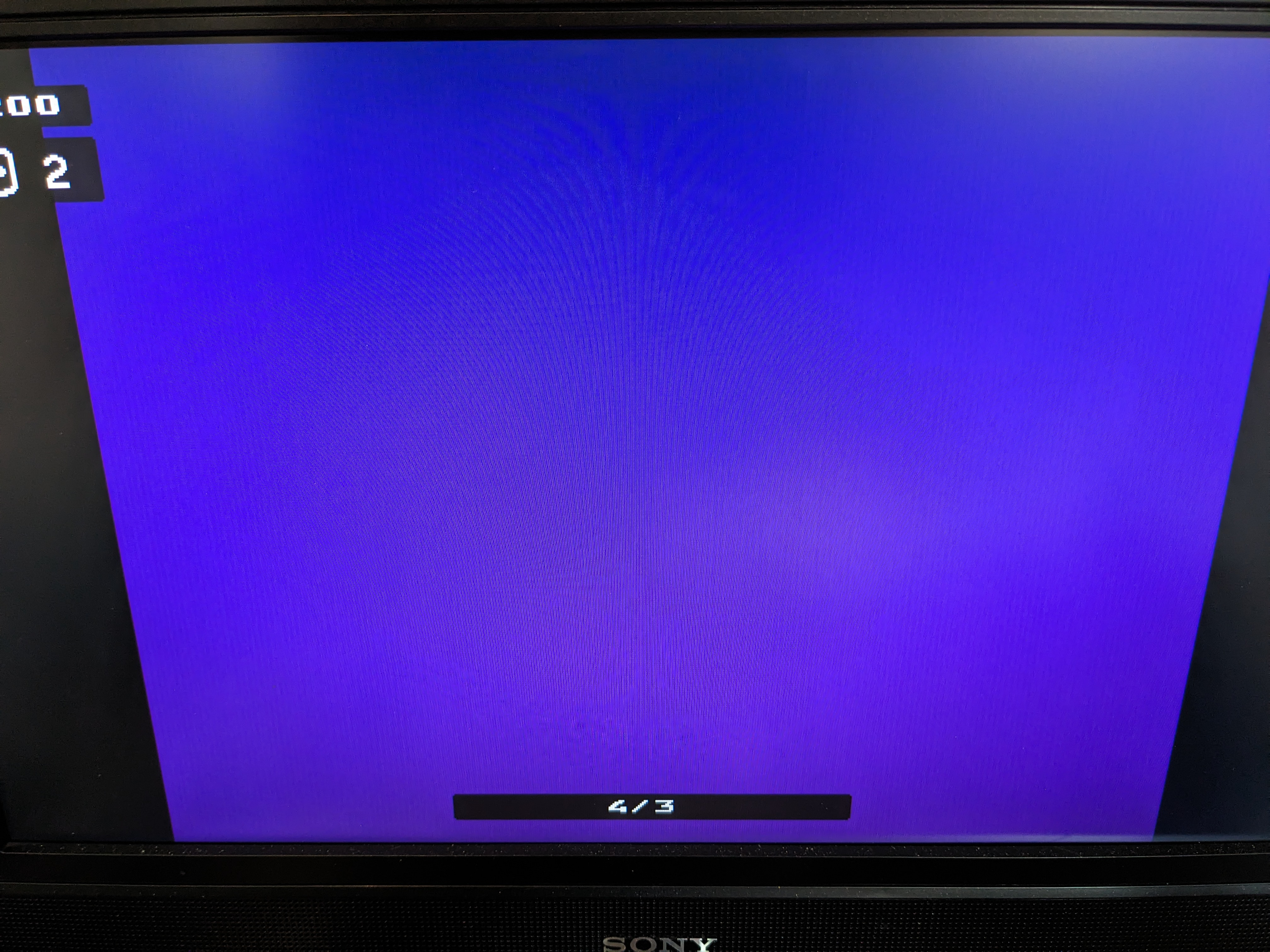
A purple screen (more purple than the photo shows). That’s new. Time to break out DiagROM. With DiagROM installed, I got a purple screen, followed by purple colour patterns.
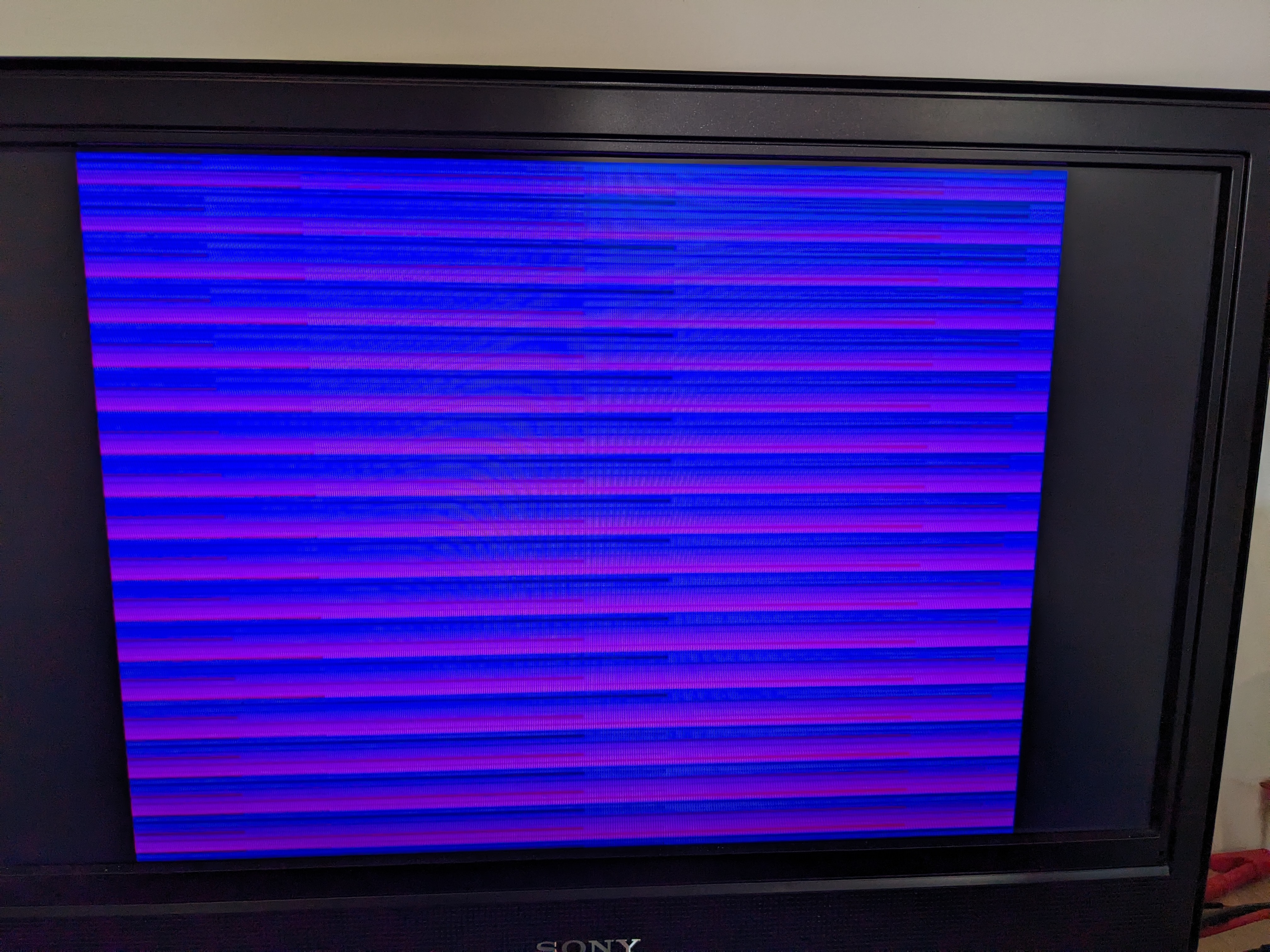

This indicates something is happening at least. So, I hooked up the serial port to my laptop to see what was showing.
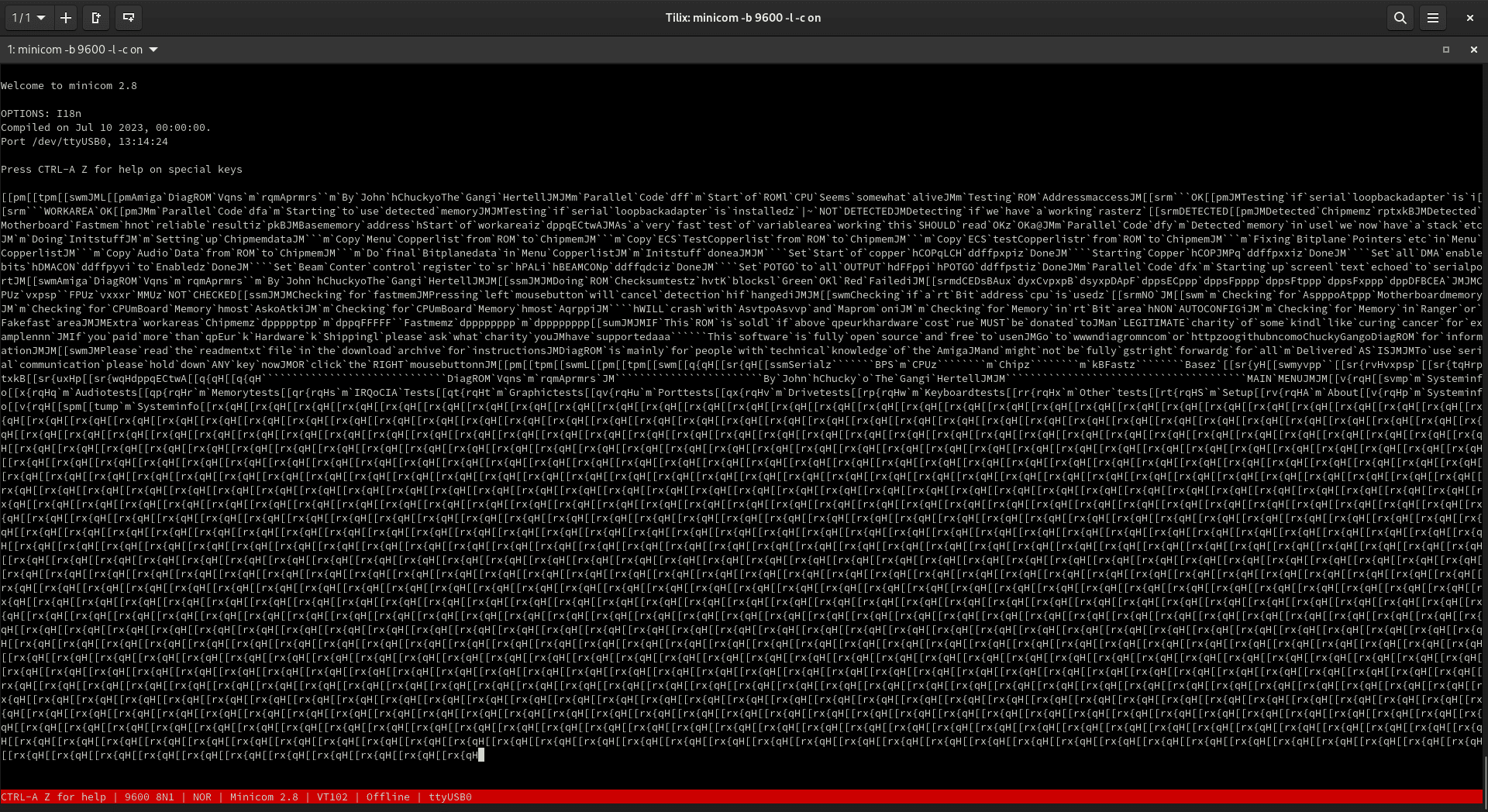
This is the DiagROM text, but a bit scrambled. The key to figuring out what the problem is, is to look at what is happening with the spaces. They are being converted to backticks. A space is hex 0x20 or 00100000 in binary and a backtick is 0x60 which is 01100000. This indicates that bit 6 (if you start from zero) is stuck on, it doesn’t affect the letters because for ASCII letters that bit is 1 anyway.
This likely is not a problem with the main data bus because instructions appear to be executing fine. It is therefore more likely an issue with the data bus between the custom chips. The fact that the colours are off is likely related, the video uses the same bus. But as yet, I’ve not been able to find anything that will cause this.
Unfortunately, for now, I’m stuck. I’m going to have to visit this fresh another day. But I welcome input from anyone who knows this bus better than I.
Leave a Reply